Surgical instrument guide device

a guide device and surgical instrument technology, applied in the field of surgical instruments, can solve the problems of difficult operation and use of endoscopic and laparoscopic instruments, difficulty in mastering common tasks such as suturing, knotting and fine dissection, and still not providing enough dexterity to allow the surgeon. to achieve the effect of greater dexterity

Active Publication Date: 2013-04-02
CAMBRIDGE ENDOSCOPIC DEVICES
View PDF105 Cites 847 Cited by
  • Summary
  • Abstract
  • Description
  • Claims
  • Application Information

AI Technical Summary

Benefits of technology

[0016]In accordance with a further embodiment of the invention there is provided a guide device for controlling a manual instrument that has a handle instrument shaft and distal tool, comprising, a proximal control handle, a guide shaft and proximal and distal bendable members that respectively intercouple the proximal and distal bendable members, cable actuation means disposed between the bendable members, for controlling the positioning of the distal tool, and a locking mechanism having locked and unlocked positions with the locking mechanism including a ball and socket arrangement disposed about the proximal motion member and a cinch member for locking the ball and socket arrangement. The locking mechanism may comprise a ball member and a compressible hub that defines a socket member. The hub is preferably a split hub and the locking mechanism further includes a cinch ring disposed about the split hub and a locking lever mounted on said cinch ring for closing said cinch ring about said hub to lock the hub against said ball member. The cinch ring preferably interlocks with the hub but is able to rotate relative thereto when in the unlocked position. A rotation knob may be supported by the hub.

Problems solved by technology

Endoscopic and laparoscopic instruments currently available in the market are extremely difficult to learn to operate and use, mainly due to a lack of dexterity in their use.
As a result, common tasks such as suturing, knotting and fine dissection have become challenging to master.
However, even so these instruments still do not provide enough dexterity to allow the surgeon to perform common tasks such as suturing, particularly at any arbitrarily selected orientation.

Method used


Image

  • Surgical instrument guide device
  • Surgical instrument guide device
  • Surgical instrument guide device

Examples


first embodiment

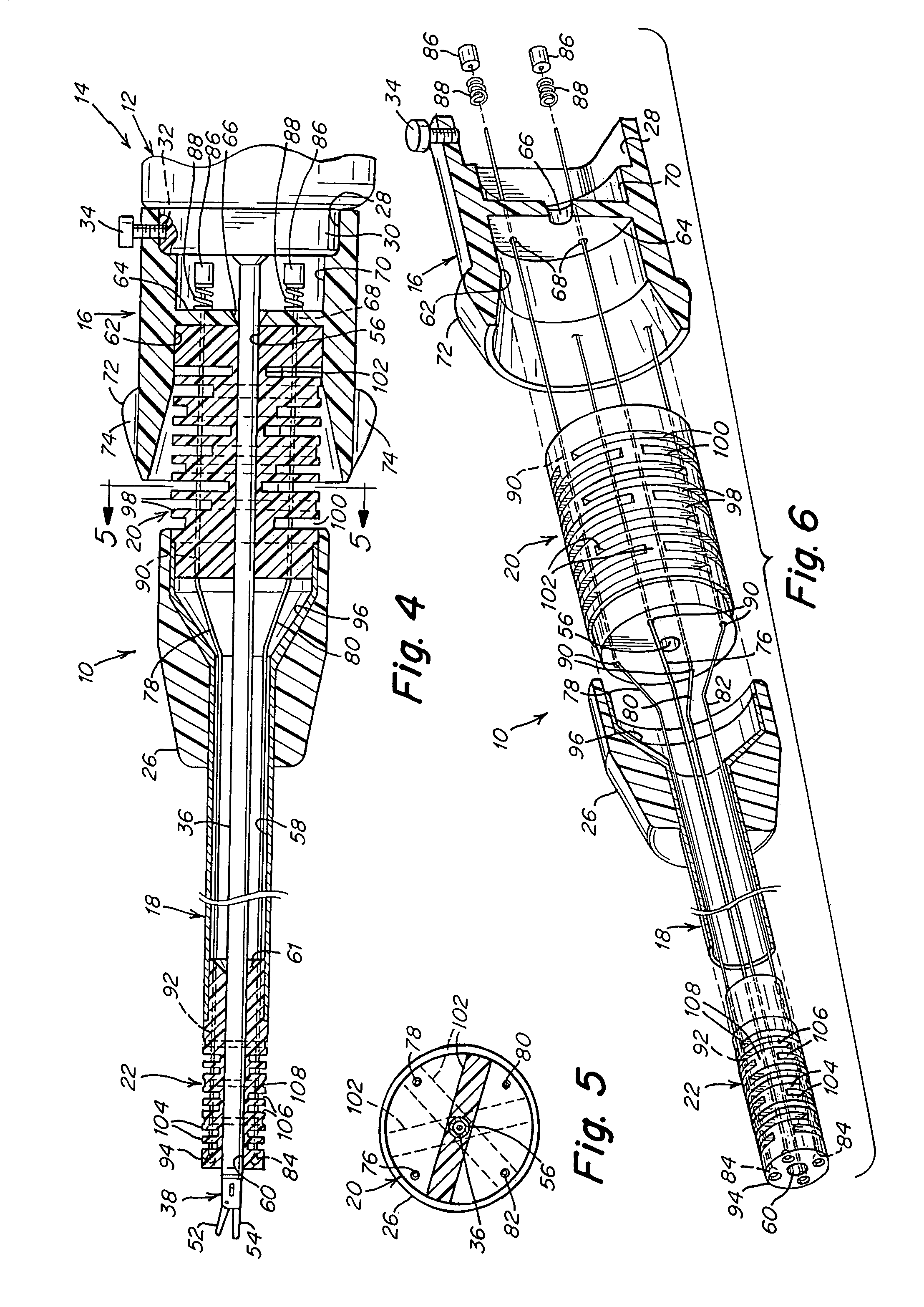
[0072]This first embodiment also discloses the details of the proximal and distal bendable members 20 and 22, particularly in FIGS. 4-6. Bendable member 20 has a central passage 56 through which the instrument shaft 36 can extend. FIG. 4 also illustrates the lumen 58 defined by the guide shaft 18 with the instrument shaft 36 extending therethrough. Similarly, the distal bendable member 22 includes a passage 60 for receiving the instrument shaft 36. In FIG. 4 the guide shaft 18 is shown as rigid, but could also be partially rigid or flexible. The guide shaft 18 may be made of a light weight metal material or of plastic.

[0073]The grip 16 includes a cavity 62 (see FIG. 6) for receiving one end of the proximal bendable member 20. This bendable member 20 is seated at the end wall 64 of the grip 16. The wall 64 has a tapered or conical passage 66 for receiving the instrument shaft 36. As depicted in FIG. 6, there are also provided several passages 68 for cabling. The grip 16 also includes...

third embodiment

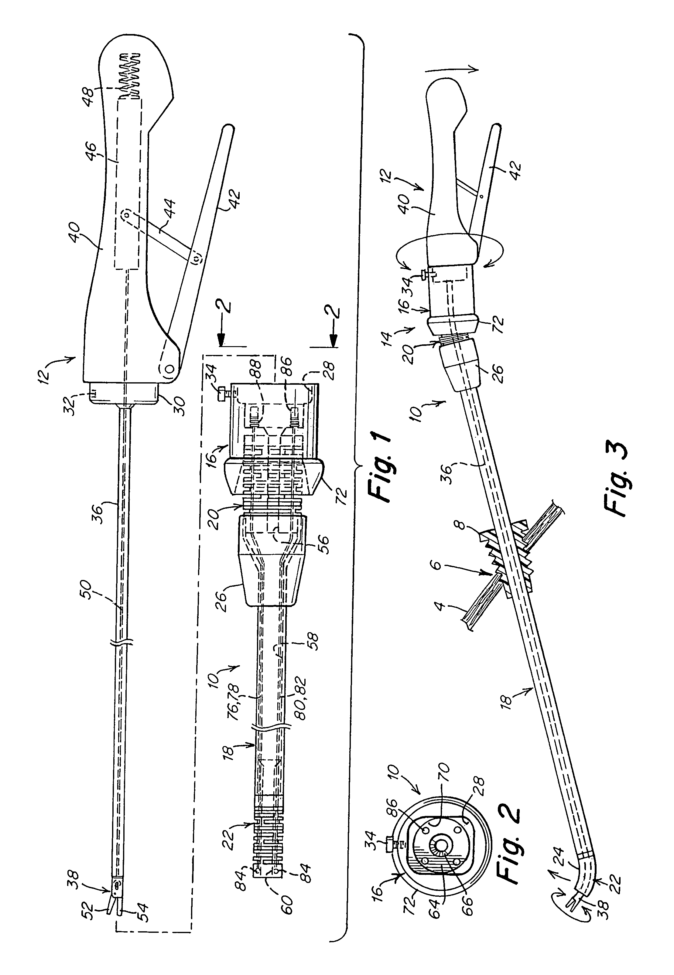
[0080]the present invention is shown in FIG. 11 illustrating a flexible or partially flexible guide shaft or tube 126. In the first two embodiments the guide shafts can be rigid or partially flexible and the instrument shaft should be at least partially flexible so as to flex when the bendable members are in action. The embodiment illustrated in FIG. 11 is meant to use a flexible or semi-flexible guide tube 126. This is illustrated as being placed through a cannula 8 at an insertion site 6 of the patient's skin 4, such as for laparoscopic use. FIG. 11 also schematically illustrates the instrument handle 12, the grip and the proximal and distal bendable members 20 and 22. Other than the guide shaft 126, the rest of the guide member may be substantially identical to that described in either FIG. 1-8 or 9 and 10. This particular embodiment also lends itself to use of the instrument and guide assembly intraluminally, such a through an incision or natural body orifice. The end effector m...

fifth embodiment

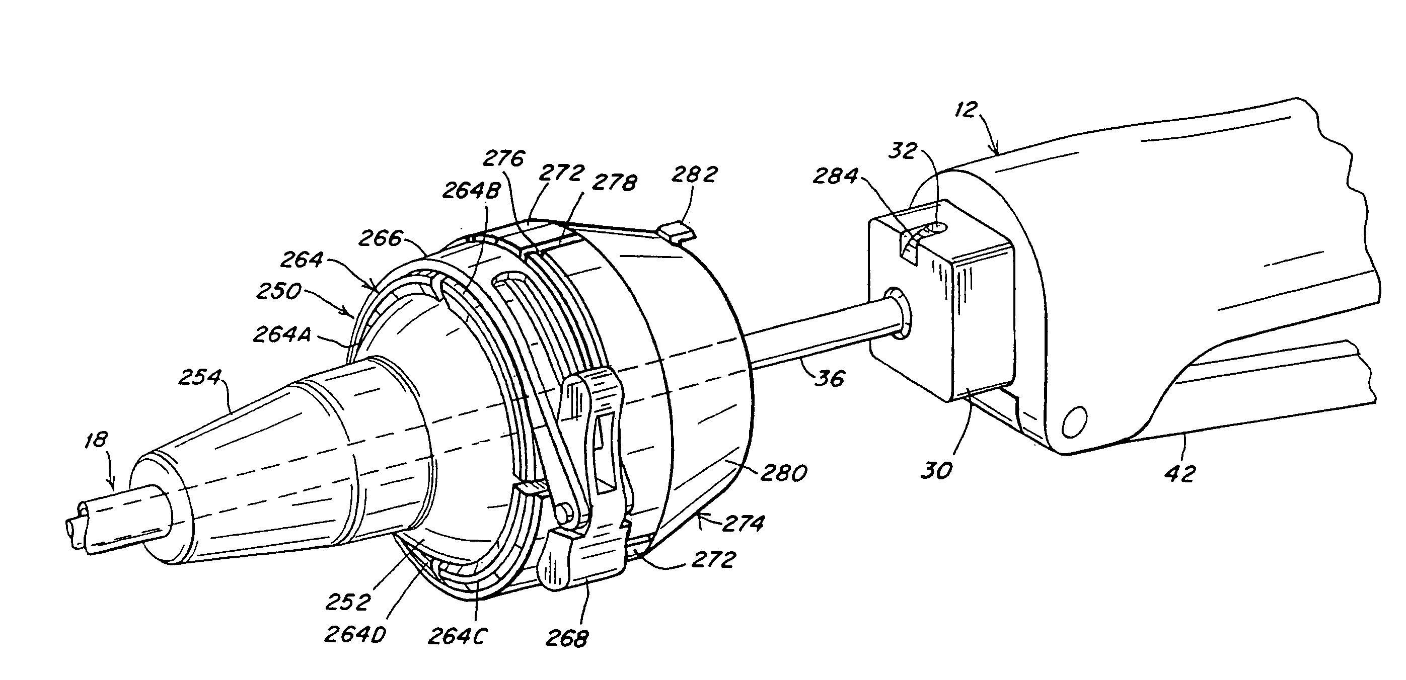
[0086]A fifth embodiment is shown in FIGS. 15-17 in which the guide member operates as before, but the additional feature is the support of the instrument that allows a sliding action of the instrument within the guide member, as well as a rotation of the instrument. When the instrument is engaged with the guide member the bending motions can be transferred as in earlier embodiments. In addition the user can move the instrument linearly in and out within the guide member, and can rotate the instrument within the guide member. This embodiment is, in particular, advantageous for intraluminal use of the instrument assembly where is may be desirable to have the capability to linearly move the instrument within a body lumen.

[0087]FIG. 15 is an exploded side view of the fifth embodiment of the guide device with a third embodiment of the surgical instrument. FIG. 16 is a view of the proximal end of the guide device of FIG. 15, as taken along line 16-16 of FIG. 15. FIG. 17 is a schematic si...


PUM


Abstract

An instrument guide device comprises an elongated guide shaft having proximal and distal ends and including an instrument lumen for receiving therethrough a manually operated instrument having an instrument shaft. A distal bendable member is disposed at the distal end of the guide shaft and a proximal bendable member is disposed at the proximal end of the guide shaft. Actuation means extends between the distal and proximal bendable members and provides a bending of the distal bendable member controlled from the proximal bendable member. The proximal bendable member is controlled from the manually operated instrument to cause a corresponding bending of said distal bendable member. A locking mechanism has locked and unlocked positions and includes a ball and socket arrangement disposed about the proximal bendable member and a cinch member for locking the ball and socket arrangement.

Description

RELATED APPLICATIONS[0001]The present application is a continuation-in-part of U.S. application Ser. No. 11 / 242,642 filed Oct. 3, 2005 now U.S. Pat. No. 7,842,028, which, in turn, claims priority to earlier filed U.S. Provisional Application 60 / 700,776, filed on Jul. 20, 2005. The present invention also relates to earlier filed U.S. application Ser. No. 10 / 822,081, filed on Apr. 12, 2004 which, in turn, claims priority to U.S. Provisional Application Ser. No. 60 / 515,560, filed on Oct. 30, 2003, as well as U.S. application Ser. No. 11 / 185,911, filed on Jul. 20, 2005 which, in turn, claims priority to U.S. Provisional Application Ser. No. 60 / 671,189, filed on Apr. 14, 2005. The content of all of the aforementioned applications are hereby incorporated by reference herein in their entirety.TECHNICAL FIELD[0002]The present invention relates in general to surgical instruments, and more particularly to manually-operated surgical instruments that are intended for use in minimally invasive s...

Claims


Application Information

Patent Timeline
Patent Type & Authority Patents(United States)
IPC IPC(8): A61B1/01
CPCA61B17/062A61B17/2909A61B17/3421A61B1/00133A61B1/0052A61B1/0057A61B2017/2905A61B17/1285A61B17/3403A61B17/3417A61B2017/003A61B2017/00477A61B2017/2906A61B2017/291A61B2017/2927A61B2017/2929A61B2017/3445A61B1/00154A61B17/068A61B1/00042
Inventor LEE, WOOJINCHAMORRO, ANDRES
Owner CAMBRIDGE ENDOSCOPIC DEVICES
Why Eureka
Try Eureka