Image-pickup display device having optical element provided with diffraction element portion

a technology of optical elements and display devices, which is applied in the direction of closed circuit television systems, television systems, instruments, etc., can solve the problem of giving viewers the feeling of incongruity

Inactive Publication Date: 2013-04-02
CANON KK
View PDF13 Cites 16 Cited by
  • Summary
  • Abstract
  • Description
  • Claims
  • Application Information

AI Technical Summary

Benefits of technology

[0008]The present invention provides an image-pickup display device (a video see-through HMD) which is compact and lightweight and is capable of viewing an image without a feeling of incongruity.

Problems solved by technology

Especially, in the HMD disclosed in Japanese Patent No. 3604990, a position of the second prism is displaced with respect to the first prism due to a manufacturing error, a feeling of incongruity is given to the viewer because the displacement between the displayed external viewed via the displayed image and the real external or the position displacement of the CG image with respect to the displayed external becomes marked.

Method used


Image

  • Image-pickup display device having optical element provided with diffraction element portion
  • Image-pickup display device having optical element provided with diffraction element portion
  • Image-pickup display device having optical element provided with diffraction element portion

Examples


Embodiment Construction

[0021]Exemplary embodiments of the present invention will be described below with reference to the accompanied drawings. First of all, a basic concept of an embodiment of the present invention will be described.

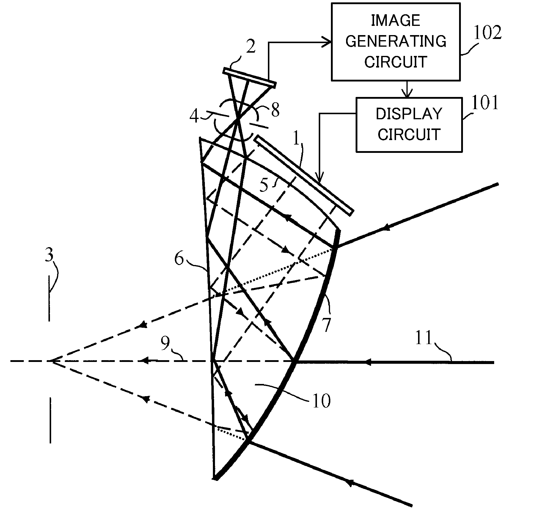
[0022]FIG. 1 illustrates a configuration of a video see-through HMD (an image-pickup display device) that is an embodiment of the present invention.

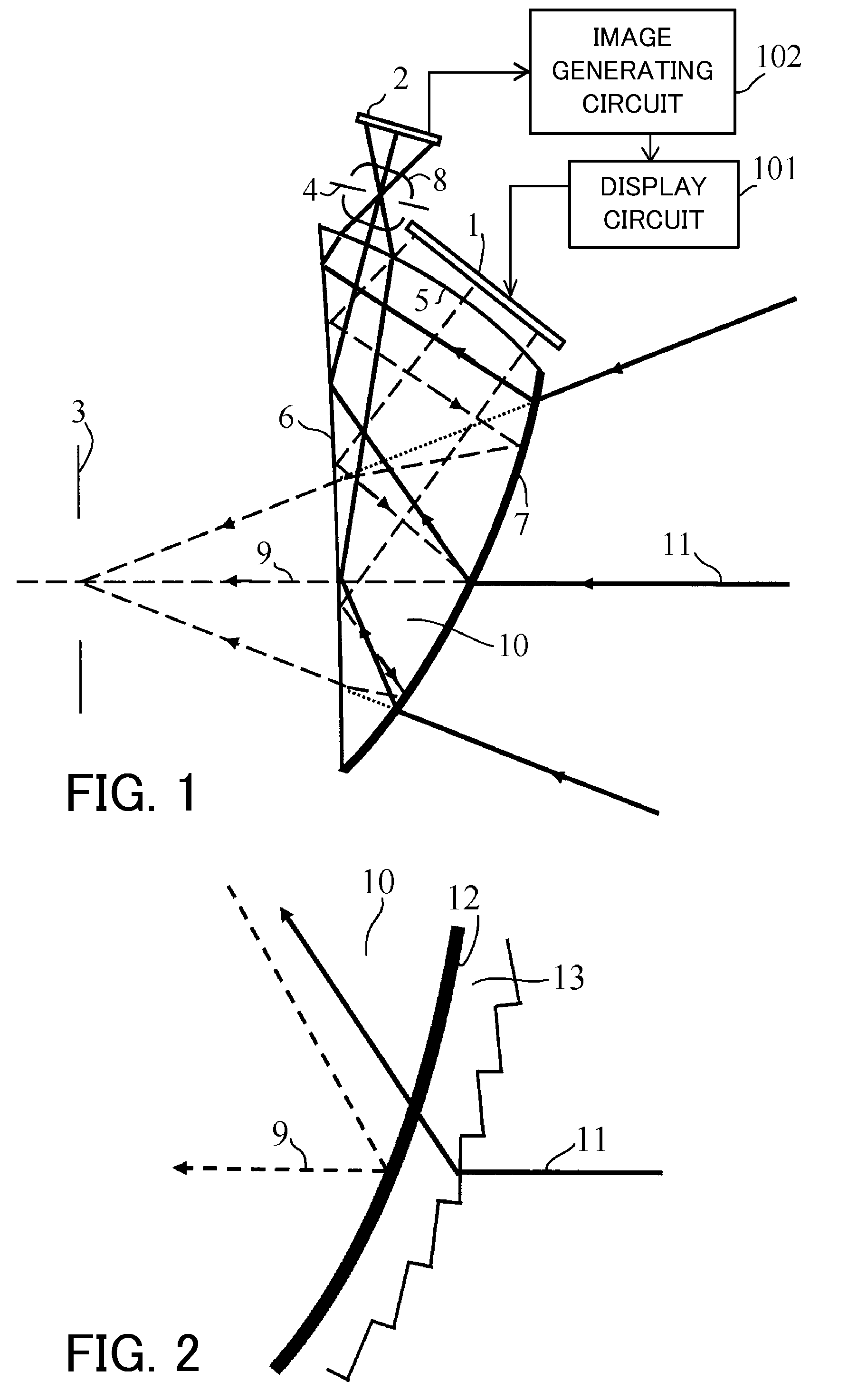
[0023]Reference numeral 10 denotes a prism as an optical element, which includes a surface (a third surface) 5, a surface (a second surface) 6, and a surface (a first surface) 7, and the insides of these three optical surfaces 5 to 7 are filled with a transmissive medium having a refractive index n larger than 1. The surface 7 is an external side surface, i.e. a surface facing the external, and the surface 6 of the three surfaces 5 to 7 is a surface that is the closest to (faces) an exit pupil 3 at which the eye of a viewer (not shown) is disposed. The surface 5 is a surface different from the surfaces 6 and 7, and faces a display...


PUM


Abstract

An image-pickup display device includes an optical system which guides lights from a display element 1 to an exit pupil 3 and from an external to an image-pickup element 2. The optical system includes an optical element 10 which is filled with a medium having a refractive index larger than 1. The optical element includes a first surface 7 at an external side and includes a diffraction element portion 13. The optical system guides the light from the display element to the exit pupil via reflection on a second surface 5 and the first surface and via transmission on the second surface, and diffracts the light from the external in the diffraction element portion to be transmitted through the first surface to enter the optical element, and is reflected on the second surface to be transmitted through a third surface 5 to be guided to the image-pickup element.

Description

BACKGROUND OF THE INVENTION[0001]1. Field of the Invention[0002]The present invention relates to an image-pickup display device that is a video see-through head mounted display (HMD) which is mounted on a head of a viewer and displays an image obtained by taking an external image to view it.[0003]2. Description of the Related Art[0004]Japanese Patent Laid-open No. H10-239628 and Japanese Patent No. 3604990 disclose the video see-through HMD as described above. The HMD includes a first prism that constitutes a displaying optical system which guides light from a display element displaying an original image to an exit pupil, i.e. the eye of a viewer, and a second prism that is disposed at an external side of the first prism and that reflects the light from the external to bend its optical path. The second prism forms an image-pickup optical system which is different from the displaying optical system, and guides the light from the external to the image-pickup element. Japanese Patent L...

Claims


Application Information

Patent Timeline
Patent Type & Authority Patents(United States)
IPC IPC(8): G02B27/14
CPCG02B27/0172H04N5/2254G02B5/18G02B2027/0138
Inventor SAITO, KENICHI
Owner CANON KK
Why Eureka
Try Eureka