Wide angle and high resolution tiled head-mounted display device
a display device and wide angle technology, applied in static indicating devices, instruments, optics, etc., can solve the problems of large exit pupil diameter and high resolution, difficult to meet the requirements of large field of view and high resolution simultaneously in a conventional head-mounted display device employing a single display channel, image distortion on the pupil plane of the display located at the edges, etc., to avoid pupil aberration, no resolution variance, and keep the pupil diameter and eye clearance constant
- Summary
- Abstract
- Description
- Claims
- Application Information
AI Technical Summary
Benefits of technology
Problems solved by technology
Method used
Image
Examples
first embodiment
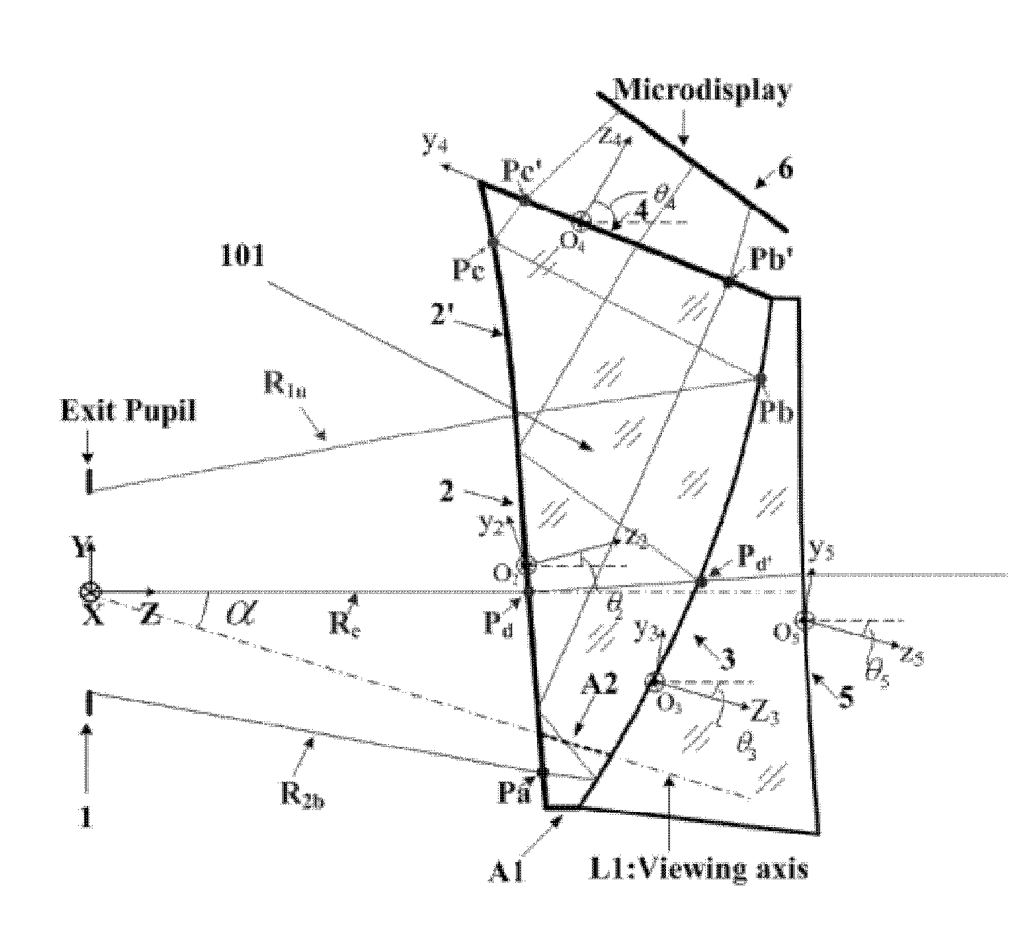
[0064]FIG. 5a is a schematic view of a tiled head-mounted display system according to a first embodiment of the present invention; FIG. 5b is a schematic view illustrating field of view of the tiled head-mounted display system according to a first embodiment of the present invention. As shown in FIG. 5a, a head-mounted display device according to the first embodiment of the present invention can comprise a first display channel 501 and a second display channel 502 tiled by the first mechanical tiling method as described above. The first display channel 501 is rotated by a first angle in YOZ plane about X-axis of a global coordinate system. The second display channel 502 is rotated by ±180° about Z axis which is in a direction along viewing axis of a human eye, and then rotated by the first angle in the opposite direction about X-axis of the global coordinate system. As shown in FIG. 5b, the tiled head-mounted display according to the first embodiment of the present invention has a h...
second embodiment
[0065]FIG. 6a is a schematic view of a tiled head-mounted display system according to a second embodiment of the present invention; FIG. 6b is a schematic view illustrating field of view of the tiled head-mounted display system according to a second embodiment of the present invention. As shown in FIG. 6a, a head-mounted display device according to the second embodiment of the present invention can comprise a first display channel 601 and a second display channel 602 tiled by the second mechanical tiling method as described above. The first display channel 601 is rotated by a second angle in XOZ plane about Y-axis of a global coordinate system. The second display channel 602 is rotated by the second angle in the opposite direction about Y-axis of the global coordinate system. As shown in FIG. 6b, the tiled head-mounted display according to the second embodiment of the present invention has a horizontal field of view of at least 70° and a vertical field of view of at least 30°.
third embodiment
[0066]FIG. 7a is a schematic view of a tiled head-mounted display system according to a third embodiment of the present invention; FIG. 7b is a schematic view illustrating field of view of the tiled head-mounted display system according to a third embodiment of the present invention. As shown in FIG. 7a, a head-mounted display device according to the third embodiment of the present invention can comprise a first display channel 701, a second display channel 702 and a third display channel 703 rotated by a predetermined angle about Y-axis of a global coordinate system. The second display channel 702 is tiled with the first display channel 701 and the third display channel 703 using the second mechanical tiling method, respectively. As shown in FIG. 7b, the tiled head-mounted display according to the third embodiment of the present invention has a horizontal field of view of at least 100° and a vertical field of view of at least 30°.
PUM
 Abstract
Description
Claims
Application Information
 - R&D
- Intellectual Property
- Life Sciences
- Materials
- Tech Scout
- Unparalleled Data Quality
- Higher Quality Content
- 60% Fewer Hallucinations
Browse by: Latest US Patents, China's latest patents, Technical Efficacy Thesaurus, Application Domain, Technology Topic, Popular Technical Reports.
© 2025 PatSnap. All rights reserved.Legal|Privacy policy|Modern Slavery Act Transparency Statement|Sitemap|About US| Contact US: help@patsnap.com


