Illumination system with variable adjustment of the illumination

a technology of illumination and adjustment, applied in the field of illumination systems, can solve the problems of affecting the illumination effect, and affecting the illumination effect, and limiting the illumination effect to certain types of illumination settings, namely, annular and quadrupolar illumination

Inactive Publication Date: 2002-09-26
CARL ZEISS SMT GMBH
View PDF0 Cites 108 Cited by
  • Summary
  • Abstract
  • Description
  • Claims
  • Application Information

AI Technical Summary

Problems solved by technology

The light distribution in the exit pupil is controlled by a diaphragm wheel, which involves a considerable loss of light.
This type of variation of the illumination settings is on the one hand very costly, and on the other hand limited to certain types of illumination settings, namely, annular and quadrupolar illumination.
Therefore, it would no longer be possible to accommodate more raster elements than channels on the pupil raster element plate in the pupil plane and there would be a loss of light and light scattering by crosstalk among the channels.

Method used


Image

  • Illumination system with variable adjustment of the illumination
  • Illumination system with variable adjustment of the illumination
  • Illumination system with variable adjustment of the illumination

Examples


Embodiment Construction

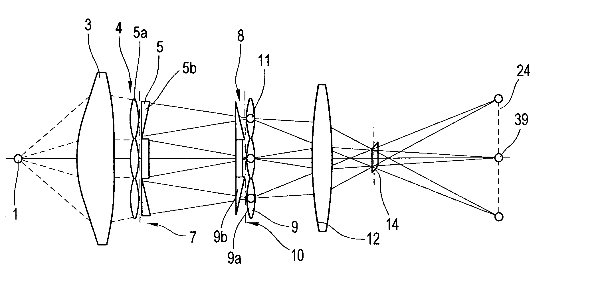
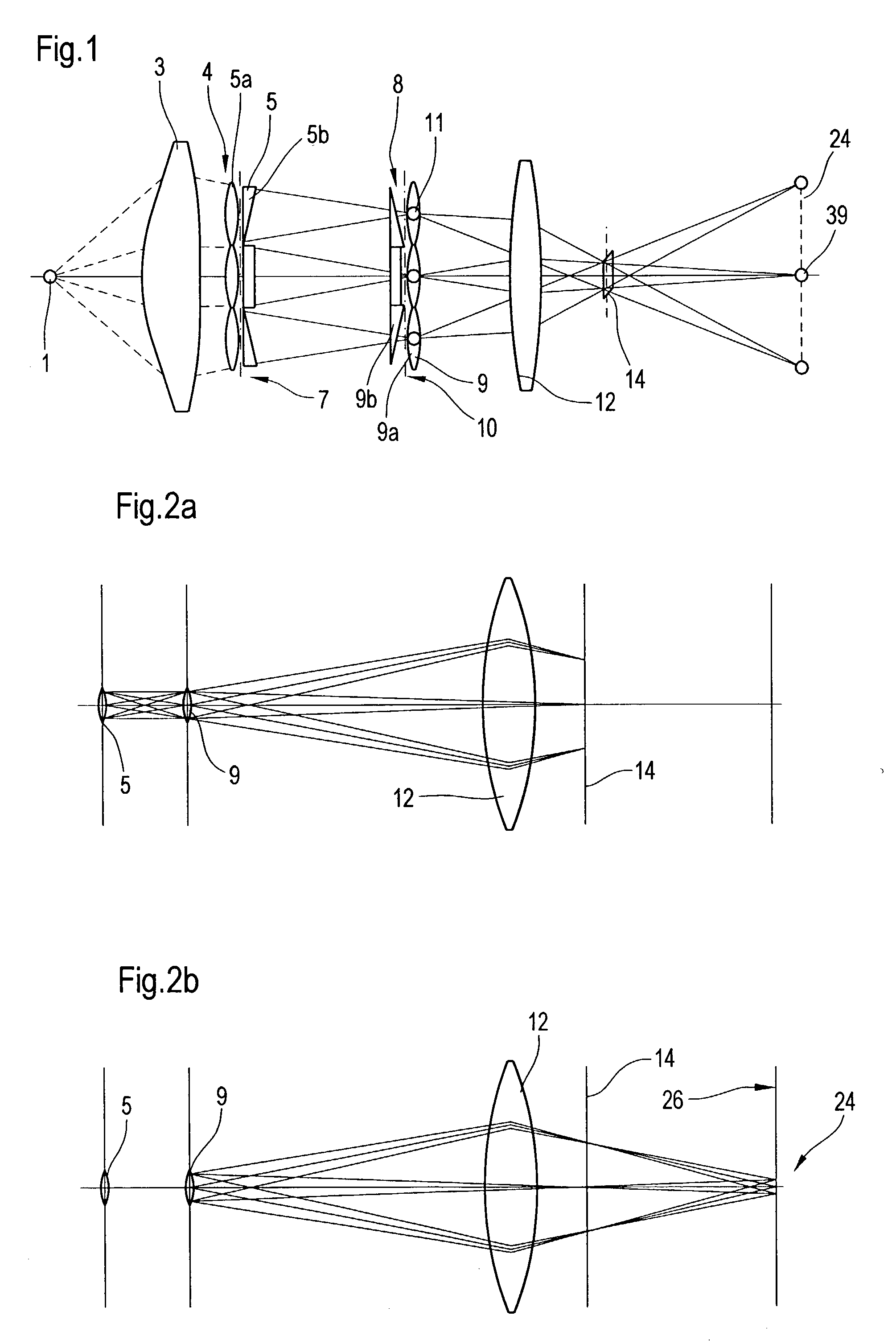
[0054] FIG. 1 shows a schematic diagram of the beam path of a system with two faceted optical elements in refractive representation. The light of a light source 1 is collected by means of a collector lens 3 and converted into a parallel or convergent light bundle. A first optical element 4 includes field raster elements 5 that are arranged on a first raster element plate 7. The field raster elements 5 divide the light bundle impinging on the first optical element 4 into a plurality of light bundles and create secondary light sources 11 in a plane, where pupil raster elements 9 of a second optical element 8 are arranged. The pupil raster elements 9 are arranged on a pupil raster element plate 10. A field lens 12 images the secondary light sources 11 in an exit pupil 24 of the illumination system or an entrance pupil of a following objective (not shown). The entrance pupil of the objective coincides with the exit pupil 24 of the illumination system. The term "Kohler illumination" is a...


PUM

PropertyMeasurementUnit
wavelengthsaaaaaaaaaa

Abstract

An illumination system comprises (a) a first optical element upon which a light beam impinges, where the first optical element has first raster elements that partition said light beam into light channels; (b) a second optical element that receives said light channels, where the second optical element has a second raster elements; (c) an object plane that receives said light channels via said second optical element; and (d) an exit pupil that is provided with an illumination via said object plane. The system is characterized by an assignment of a member of said first raster elements and a member of said second raster elements to each of said light channels to provide a continuous beam path from said first optical element to said object plane for each of said plurality of light channels. The assignment is changeable to provide an adjustment of said illumination in said exit pupil.

Description

[0001] 1. Field of the Invention[0002] The invention concerns an illumination system for wavelengths .ltoreq.193 nm, particularly for EUV lithography, a method for adjusting the illumination in an exit pupil of an illumination system, as well as a projection exposure comprising such an illumination system.[0003] 2. Description of the Prior Art[0004] In order to allow even further reduction in the line widths for electronic components, particularly in the submicron range, it is necessary to reduce the wavelength of the light used for the microlithography. For example, with wavelengths less than 193 nm, lithography with soft X-rays, so-called EUV lithography is possible.[0005] An illumination system suitable for EUV lithography should illuminate homogeneously, i.e., uniformly, the field used in EUV lithography, particularly the ring field of an objective, with as few reflections as possible, and furthermore, the pupil of the objective should be illuminated up to a particular filling r...

Claims


Application Information

Patent Timeline
Patent Type & Authority Applications(United States)
IPC IPC(8): G02B19/00G02B17/00G03F7/20G21K1/06G21K5/00G21K5/04H01L21/027
CPCB82Y10/00G03F7/70075G03F7/70083G03F7/70108G03F7/70166G03F7/702G03F7/70233G03F7/70358G03F7/70891G03F7/70983G21K1/06G21K5/00G21K5/04
Inventor SINGER, WOLFGANG
Owner CARL ZEISS SMT GMBH
Why Eureka
Try Eureka