

Insufflation device with second bypass for additional body cavity
a technology of insufflation device and body cavity, which is applied in the direction of medical devices, medical insufflators, other medical devices, etc., can solve the problems of increased increased risk of internal contamination of insufflation means, and increased risk of contamination of insufflation device, so as to increase the safety and hygiene of insufflation device, and enhance patient comfort
- Summary
- Abstract
- Description
- Claims
- Application Information
AI Technical Summary
Benefits of technology
Problems solved by technology
Method used
Image

Examples
Embodiment Construction
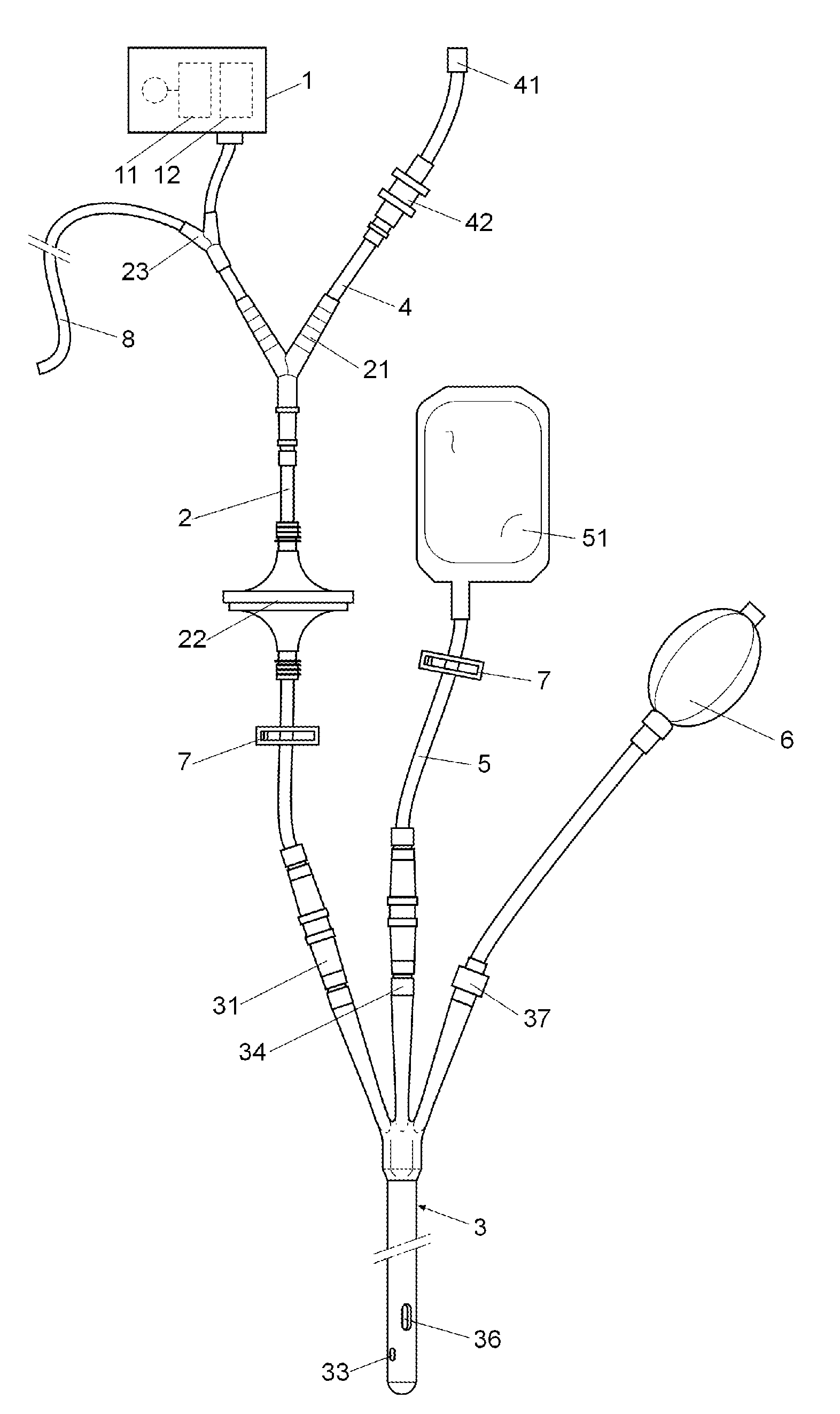
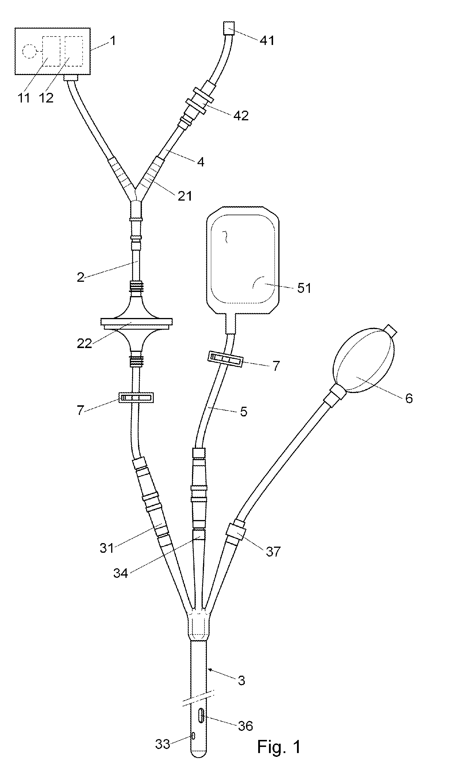
[0008]The device for insufflating gas and collecting effluents from the body cavities of an individual that is the object of this invention has technical peculiarities destined for improving the patient's comfort and ensuring the cleanliness and hygiene of the gas insufflation device.
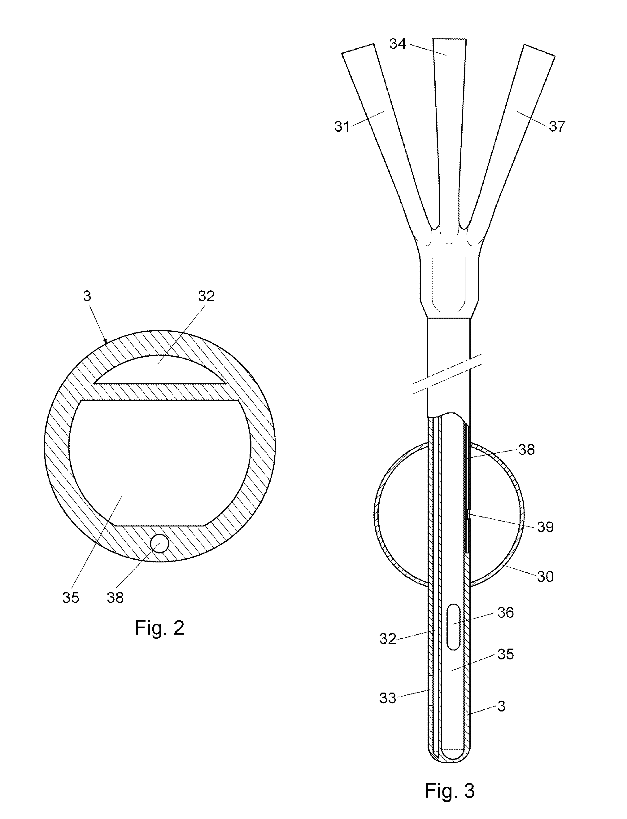
[0009]The device comprises: a gas insufflation device, a first duct for supplying the gas provided by the insufflation device towards the interior of a body cavity of an individual; barriers inserted in the first duct to prevent the passage of effluents from the individual towards the interior of the insufflation device; a deposit for collecting said effluents, a member insertable in a body cavity of the individual, attachable to the first duct and having an expandable ring-shaped element for perimetrally sealing the cavity of the individual; and means for inflating the expandable element upon introduction of the member insertable in a body cavity of an individual.
[0010]The first duct has a by-pass and ...
PUM
 Abstract
Description
Claims
Application Information