Contour guide for ice skate sharpener

a technology for contour guides and ice skates, applied in the direction of grinding machines, skating parts, sports apparatus, etc., can solve the problems of inability to achieve accurate grinding of contours and approximation of required contours

Inactive Publication Date: 2013-04-30
GUSPRO
View PDF26 Cites 12 Cited by
  • Summary
  • Abstract
  • Description
  • Claims
  • Application Information

AI Technical Summary

Problems solved by technology

Whilst this arrangement ensures a more consistent profile, the provision of the pair of wheels results in only an approximation of the required contour due to the need to space the wheels apart for the requisite stability.
As such, accurate grinding of the contour cannot be achieved.

Method used


Image

  • Contour guide for ice skate sharpener
  • Contour guide for ice skate sharpener
  • Contour guide for ice skate sharpener

Examples


Embodiment Construction

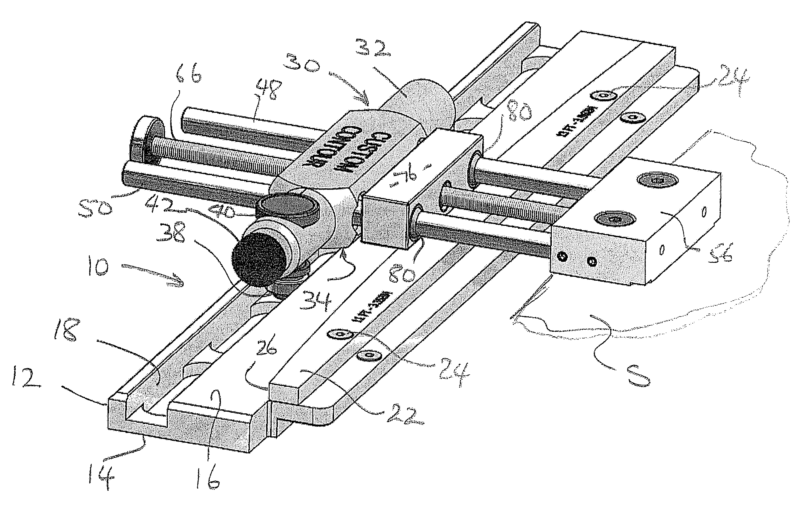
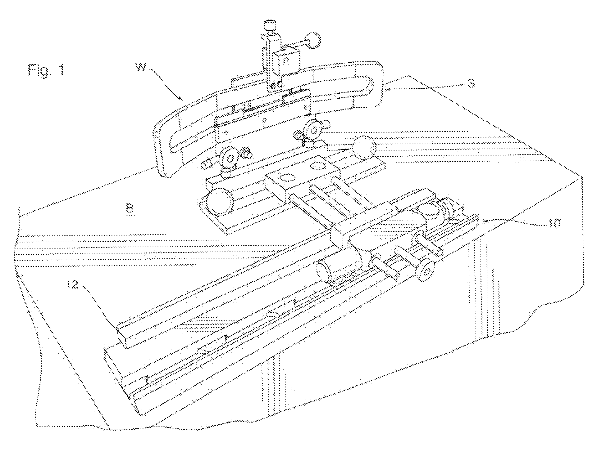
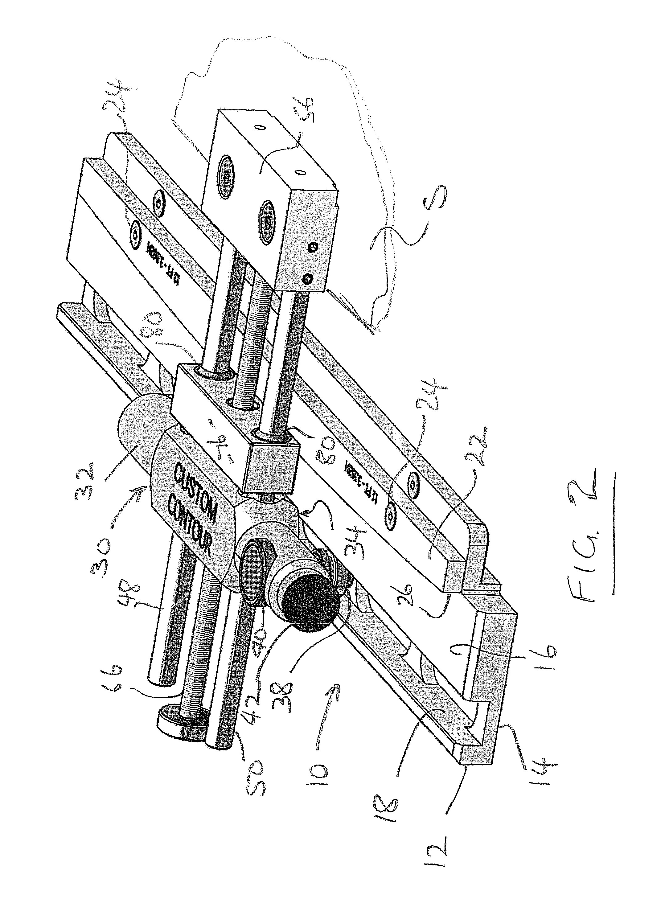
[0015]Referring therefore to FIG. 1, a guide assembly generally indicated at 10 has a base 12 with a lower surface 14 designed to slide along a bench indicated generally at (B). The guide assembly 10 is connected to a skate holder (S) which is also designed to slide on the bench (B). The form of skate holder may vary but a particularly suitable skate holder is one shown in US Pat. No. 7,473,164 the contents of which are incorporated herein by reference.

[0016]It will be appreciated that the skate holder (S) is designed to support a skate and present the edge of the blade to a grinding wheel (W) that is fixed relative to the bench (B) and rotates about a horizontal axis (as shown) on a vertical axis. The base 12 has an upper surface 16 with an elongate linear groove 18 formed adjacent a front edge 20. The vertical faces defining the groove 18 providing abutment faces that define a predetermined path. The upper surface 16 has a template 22 that is removably secured to the upper surface...


PUM

PropertyMeasurementUnit
movementaaaaaaaaaa
rotationaaaaaaaaaa
heightaaaaaaaaaa

Abstract

A guide assembly for an ice skate sharpener cooperates with a template of a desired contour of a skate blade to control the relative disposition of a sharpening wheel and a skate blade. The guide assembly comprises a base and a carriage slidably mounted on the base so as to be moveable, relative to said base, along a predefined path. A support is provided for connection to a skateholder. The support is connected to the carriage to permit movement of a skateholder in a direction normal to the path. The support inhibits relative movement between the carriage and a skateholder in a direction parallel to said path. A follower connected between the skateholder and template, control movement of the skateholder in a direction normal to the path as the carriage is moved along said predefined path. The skateholder therefore follow the contour of the template.

Description

CROSS REFERENCE TO RELATED APPLICATIONS[0001]This application claims priority from U.S. Provisional Application No. 61 / 172,061 filed on Apr. 23, 2009; the contents of which are incorporated herein by reference.FIELD OF THE INVENTION[0002]The present invention relates to a guide for use with an ice skate sharpener.SUMMARY OF THE INVENTION[0003]The blades of an ice skate need to be frequently sharpened in order to maintain optimum performance. The sharpening is normally done by passing the blade past a grinding wheel and must be done with great precision. The blade edge will have a transverse concave profile to provide a pair of laterally spaced edges. The cross section of the profile is determined by the shape of the grinding wheel and must be aligned with the centre line of the blade itself to provide edges at the same height. Moreover, the blade has a contour along its length so that the lower edge of the blade is radiused from tip to heel. The contour of the blade will vary accord...

Claims


Application Information

Patent Timeline
Patent Type & Authority Patents(United States)
IPC IPC(8): B24B7/00
CPCB24B3/003B24B41/06
Inventor MOON, ROBERT
Owner GUSPRO
Why Eureka
Try Eureka