Proximity sensor

a proximity sensor and sensor technology, applied in the field of proximity sensors, can solve the problems of changing the oscillation conditions of the parallel resonant circuit, unable to provide a distance signal corresponding to the distance between, and proximity sensors cannot show how close the object approached the sensing coil, etc., to achieve the effect of improving noise resistance, reducing cost, and improving sensing accuracy

Inactive Publication Date: 2013-04-30
PANASONIC CORP
View PDF16 Cites 28 Cited by
  • Summary
  • Abstract
  • Description
  • Claims
  • Application Information

AI Technical Summary

Benefits of technology

[0009]In an embodiment according to the second to fourth aspects, the variable resistor circuit is a series or parallel circuit of at least one fixed resistor and at least one variable resistor. In this configuration, the resistance value of the fixed resistor can be used as an offset of the resistance value of the variable resistor circuit. Therefore a resolution of the distance (positional accuracy) between an object and the sensing coil can be improved.
[0044]In an embodiment according to the first to sixth aspects, the oscillation control circuit, the amplitude measurement circuit, the control circuit and the signal processing circuit are mounted on a monolithic IC. In this configuration, downsizing and lower cost can be implemented, and noise resistance can be improved, compared with a configuration where the oscillation control circuit, amplitude measurement circuit, control circuit and signal processing circuit are mounted on different ICs respectively.

Problems solved by technology

If this object approaches the parallel resonance circuit, an eddy circuit loss is generated in the object due to an electromagnetic induction function, which changes the impedance (effective resistance value) of the sensing coil, and also changes the oscillation conditions of the parallel resonant circuit.
This proximity sensor, however, only generates a binary signal that shows whether the object exists in a sensing range corresponding to this specified value, and cannot provide a distance signal corresponding to the distance between the object and the sensing coil.
Therefore this proximity sensor cannot show how close the object approached the sensing coil.

Method used


Image

  • Proximity sensor
  • Proximity sensor
  • Proximity sensor

Examples


tenth embodiment

(Tenth Embodiment)

[0179]FIG. 10 shows a proximity sensor according to a tenth embodiment of the present invention. The proximity sensor according to the tenth embodiment is characterized by an oscillation control circuit 2, and the other composing elements are configured in the same way as the sixth embodiment. Similar composing elements are denoted with a same reference symbol used for the sixth embodiment. A current generating circuit 21 of the oscillation control circuit 2 according to the tenth embodiment corresponds to the same component according to the fifth embodiment.

[0180]According to a variant form of the sixth to ninth embodiments, the variable resistor circuit 25 is inserted between the interval power supply (Vcc) and the transistor (Q4), and the resistor (fixed resistor) 26 is inserted between the internal power supply (Vcc) and the transistor (Q3). In this example, the feedback current (In) is given by (Rs / Rv)·Ic.

[0181]According to an example, the variable resistor ma...

eleventh embodiment

(Eleventh Embodiment)

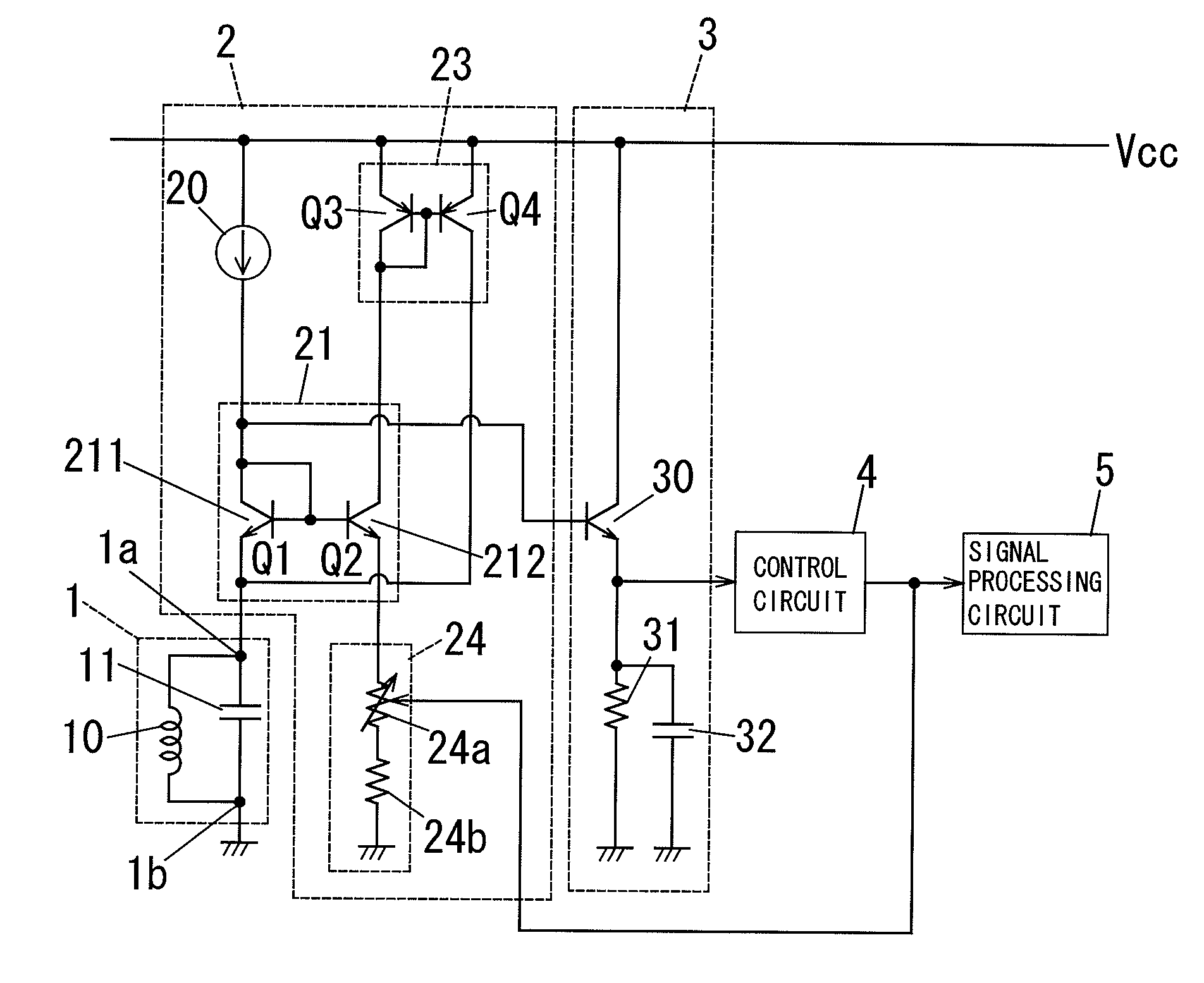
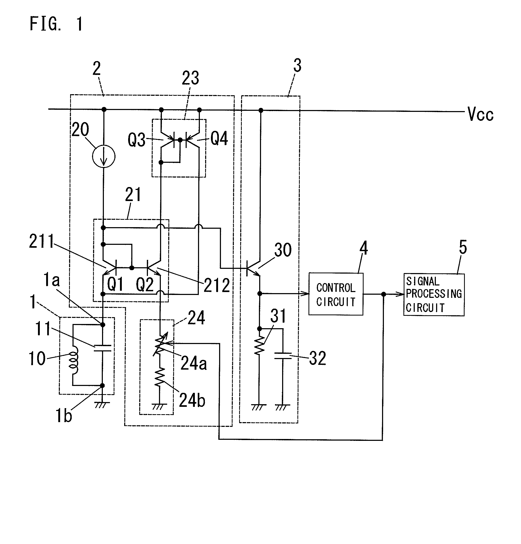
[0182]FIG. 11 shows a proximity sensor according to an eleventh embodiment of the present invention. The proximity sensor according to the eleventh embodiment is characterized by an oscillation control circuit 2 and control circuit 4, and the other composing elements are configured in the same way as the first embodiment. Similar composing elements are denoted with same reference symbols used for the first embodiment.

[0183]The oscillation control circuit 2 according to the eleventh embodiment is configured to supply an electric current to the LC resonant circuit 1 as positive feedback, and generate the oscillating voltage across the LC resonant circuit 1. In the case of the example in FIG. 11, the oscillation control circuit 2 is comprised of a bias circuit 20, level shift circuit 22, current generating circuit 21, feedback circuit 23 and resistor (fixed resistor) 24b.

[0184]The bias circuit 20 according to the eleventh embodiment is a constant current source, w...

twelfth embodiment

(Twelfth Embodiment)

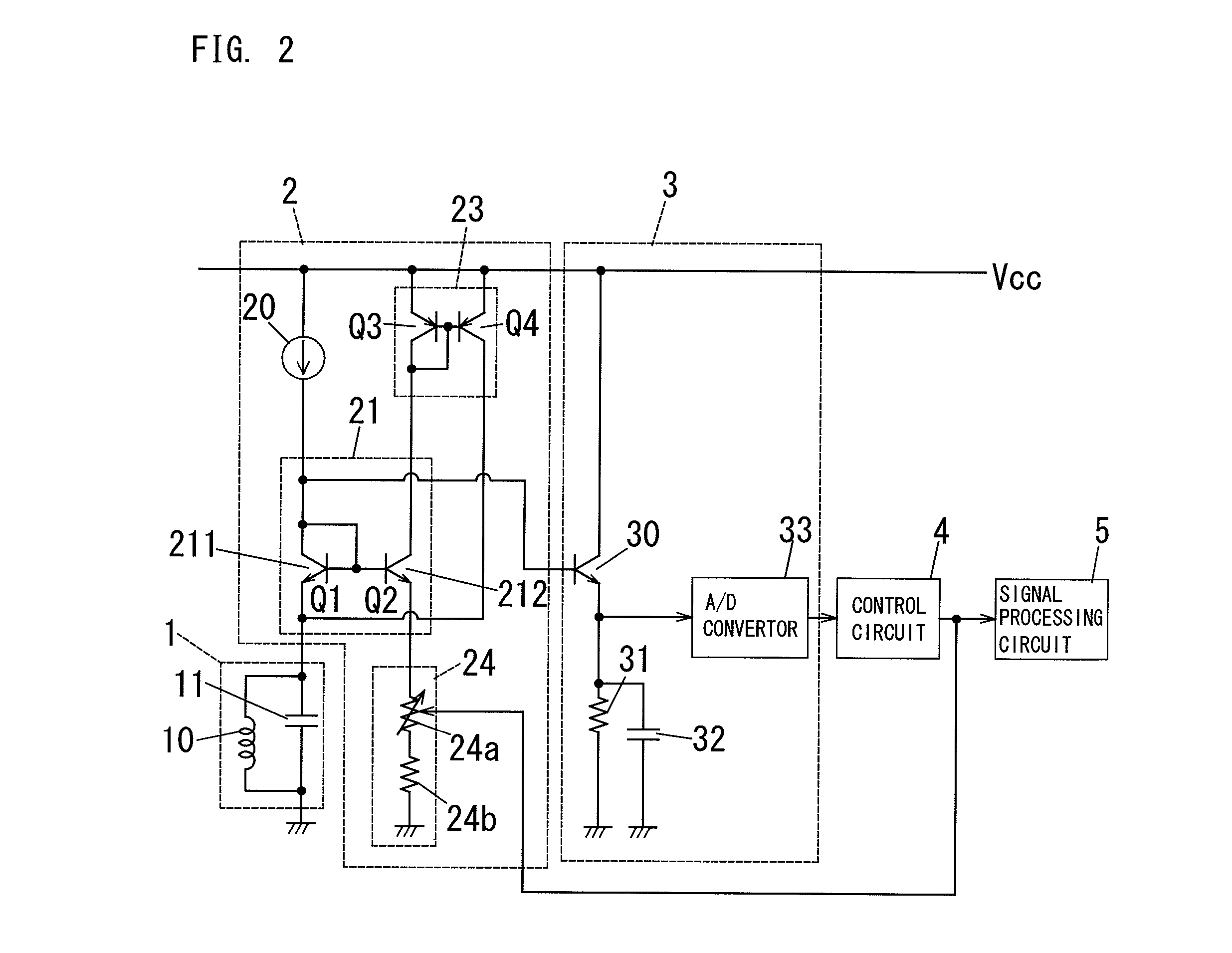
[0206]FIG. 12 shows a proximity sensor according to a twelfth embodiment of the present invention. The proximity sensor according to the twelfth embodiment is characterized by a variable resistor 21c, amplitude measurement circuit 3, control circuit 4 and signal processing circuit 5, and the other composing elements are configured in the same way as the eleventh embodiment. Similar composing elements are denoted with same reference symbols used for the eleventh embodiment.

[0207]The variable resistor 21c according to the twelfth embodiment is a digital potentiometer that can set a resistance value (Rv) using a digital code (e.g. bit string “00000111”).

[0208]The variable resistor 21c, amplitude measurement circuit 3, control circuit 4 and signal processing circuit 5 according to the twelfth embodiment correspond to the variable resistor 24a of the variable resistor circuit 24, amplitude measurement circuit 3, control circuit 4 and signal processing circuit 5 accord...


PUM


Abstract

A proximity sensor has an oscillation circuit, an amplitude measurement circuit, a control circuit and a signal processing circuit. The oscillation circuit has an LC resonant circuit and an oscillation control circuit that is configured to supply an electric current to the LC resonant circuit to generate oscillating voltage across the LC resonant circuit. The amplitude measurement circuit is configured to produce an amplitude signal corresponding to the amplitude of the oscillating voltage. The control circuit is configured to set the negative conductance of the oscillation control circuit to a critical value by which the LC resonant circuit can oscillate based on the amplitude signal. The signal processing circuit is configured to produce a distance signal corresponding to the distance between an object and the sensing coil based on a parameter associated with the negative conductance.

Description

TECHNICAL FIELD[0001]The present invention relates to a proximity sensor, and more particularly to a proximity sensor that includes an LC resonant circuit having a sensing coil and a capacitor, and is configured to generate a distance signal corresponding to a distance between an object and the sensing coil.BACKGROUND ART[0002]Japanese Patent Application Laid-Open No. 2005-295248, which was laid open to public inspection on Oct. 20, 2005, discloses a high frequency oscillation type proximity sensor, that is configured such that an object constituted by metal (conductor) or magnetic substance is sensed without contact. In concrete terms, this proximity sensor includes a parallel resonant circuit having a sensing coil and a capacitor. If this object approaches the parallel resonance circuit, an eddy circuit loss is generated in the object due to an electromagnetic induction function, which changes the impedance (effective resistance value) of the sensing coil, and also changes the osc...

Claims


Application Information

Patent Timeline
Patent Type & Authority Patents(United States)
IPC IPC(8): G01R27/28
CPCH03K17/9502H03K17/9547
Inventor NIWA, MASAHISAOKADA, KUNITAKAKASANO, FUMIHIROTAWARATSUMIDA, SUKOYA
Owner PANASONIC CORP
Why Eureka
Try Eureka