Door unit

a technology for doors and components, applied in the field of doors, can solve the problems of increased number of parts, inconvenient layout of components, and inability to meet the needs of construction workers, and achieve the effects of reducing the number of parts, facilitating the layout of components, and preventing vibration

Active Publication Date: 2013-05-14
CATEPILLAR SARL
View PDF49 Cites 15 Cited by
  • Summary
  • Abstract
  • Description
  • Claims
  • Application Information

AI Technical Summary

Benefits of technology

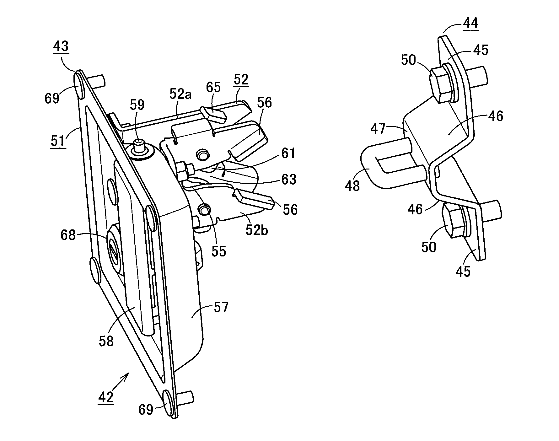
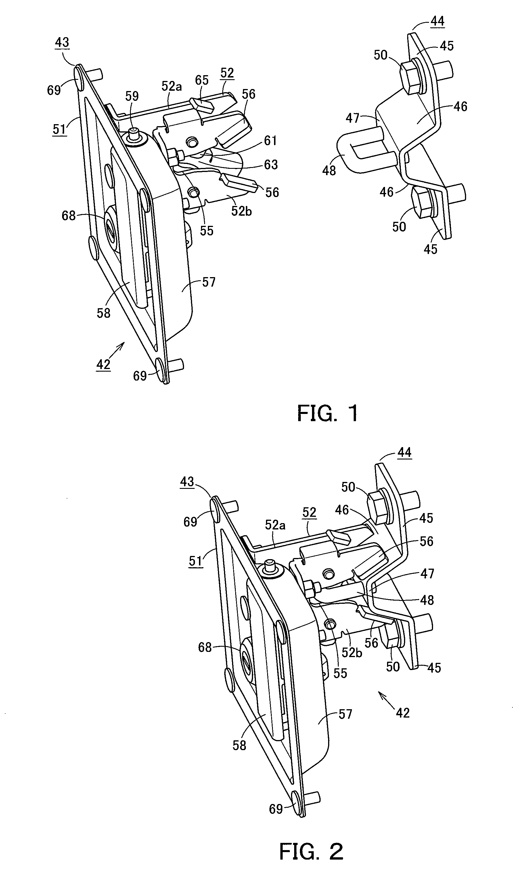
[0008]In order to solve the above problems, an object of the invention is to reduce the number of parts and also facilitate the layout of the components by integrating with a latching device a shimmy stopping member for preventing vibration of a door panel.
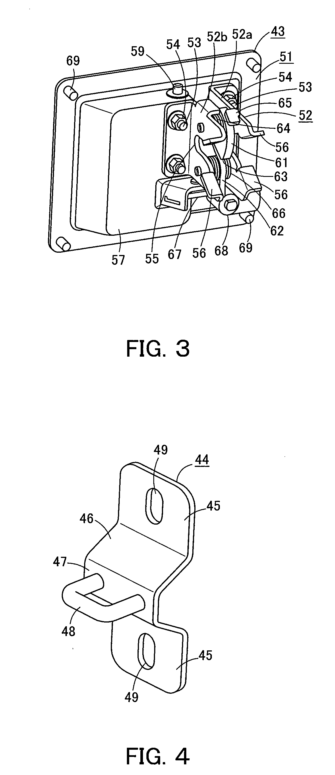
[0016]Further the second shimmy-stopping engaging portion is formed in a V-like shape at the open end of the latch groove portion, which is formed in a U-like shape by cutting away a part of the mechanism body portion. Therefore, the guiding function of the second shimmy-stopping engaging portion provides for reliable insertion of the stopper portion of the engaging member into the latch groove portion of the mechanism body portion, and the V-shaped second shimmy-stopping engaging portion is capable of restraining the first shimmy-stopping engaging portion of the engaging member. As a result, vibration of the door panel can reliably be prevented

Problems solved by technology

Providing shimmy stopping members 19 for preventing vertical vibration as separate members from the latching device 18 presents problems resulting from an increased number of parts, such as not being cost effective due to costs of parts.
Should this be the case, there may be limitations concerning the layout of the components.

Method used


Image

  • Door unit
  • Door unit
  • Door unit

Examples


Embodiment Construction

[0030]Next, the present invention is explained in detail hereunder, referring to an embodiment thereof shown in FIGS. 1 to 11.

[0031]FIG. 11 illustrates a hydraulic excavator 10, which is a work machine. The hydraulic excavator 10 includes a lower structure 11, an upper structure 12, a cab 13, a work equipment 14, and a power system 15 that includes an engine. The cab 13, the work equipment 14, and the power system 15 are mounted on the upper structure 12, which is rotatably mounted on the lower structure 11. The power system 15 is covered by a top cover 16, side doors 17, and other such components.

[0032]FIGS. 6 to 8 illustrate a door panel 20 of a side door 17. The door panel 20 includes an outer panel 21, an inner panel 23, and a foamed material 24. The inner panel 23 is formed by press molding a metal plate that is thinner than the outer panel 21 so as to have a bumpy surface with recessed portions and protruding portions. The recessed portions are fixed to the inner surface of th...


PUM


Abstract

A door panel of a side door of a machine has a latching mechanism, and a frame of the machine includes a striker. The striker includes a pair of vertically arranged mounting base portions, a pair of slanted shimmy-stopping surface portions formed on the mounting base portions so as to protrude in a V-like shape towards the latching mechanism, and a metal hooking portion protruding from a flat end portion that is provided between the slanted shimmy-stopping surface portions. The latching mechanism includes a mechanism body portion including main body plates. A U-shaped latch groove portion for engaging the metal hooking portion of the striker is formed by cutting away a part of each main body plate, and shimmy suppressing portions that are vertically arranged in a V-like shape are provided at the open end of each latch groove portion.

Description

CROSS REFERENCE TO RELATED APPLICATIONS[0001]This is a U.S. national phase application under 35 U.S.C. §371 of International Patent Application No. PCT / JP2008 / 062166, filed Jul. 4, 2008, and claims the benefit of Japanese Application No. 2007-280255, filed Oct. 29, 2007. The International Application has not been published at the time of this filing. The contents of which are incorporated herein in their entirety.TECHNICAL FIELD[0002]The present invention relates to a door unit having a door panel that is provided with a latching mechanism.BACKGROUND[0003]FIG. 12 illustrates a hydraulic excavator 10, which is a work machine. The hydraulic excavator 10 includes a lower structure 11, an upper structure 12, a cab 13, a work equipment 14, and a power system 15 that includes an engine. The cab 13, the work equipment 14, and the power system 15 are mounted on the upper structure 12, which is rotatably mounted on the lower structure 11. The power system 15 is covered by a top cover 16, sid...

Claims


Application Information

Patent Timeline
Patent Type & Authority Patents(United States)
IPC IPC(8): E05C3/06E05C17/44E05C19/00E05B15/02E05B85/24E02F9/00E05B77/36E05B83/16E05C19/06
CPCE02F9/00E02F9/0891E05B85/02E05B85/045E05C3/24Y10T292/1047Y10T292/1064Y10T292/108Y10T292/68Y10T292/71
Inventor UTO, RYOJITAKEUCHI, SHIGEMI
Owner CATEPILLAR SARL
Why Eureka
Try Eureka