
Ulna fixation

a technology of ulna and ulna, which is applied in the field of surgical devices and methods for the fixation of fractured bones, can solve the problems of proximal ulna, dislocation or subluxation, elbow instability, etc., and achieve the effect of secure application of the plate to the bon

Inactive Publication Date: 2013-05-14
GELFAND JEFFREY DR
View PDF2 Cites 55 Cited by
  • Summary
  • Abstract
  • Description
  • Claims
  • Application Information

AI Technical Summary

Benefits of technology

The invention provides a bone plate specifically designed for the rigid fixation of a coronoid process fracture in the proximal ulna. The plate has hooked features that fit snugly around the bone, providing stability. The plate can be secured to the bone using bone screws, sutures, cables, or other flexible devices. The plate has elongated holes for bone screws or other fixation methods, and may also contain a recess or lip around the perimeter of the hole to receive an anchor. The invention also includes a method for securing the plate to the bone using a low-profile targeting guide and bone drill. The technical effects of the invention include improved stability and reduced risk of complications during surgery, as well as improved outcomes for patients with coronoid process fractures.

Problems solved by technology

Coronoid fractures of the proximal ulna may be associated with elbow instability.
If there is associated ligamentous injury about the elbow, the joint will often become unstable and result in dislocation or subluxation.
Because of the small fragment size of the coronoid and its location deep to the soft tissues in the anterior aspect of the elbow, standard methods of fracture fixation are challenging.

Method used


Image

  • Ulna fixation
  • Ulna fixation
  • Ulna fixation

Examples

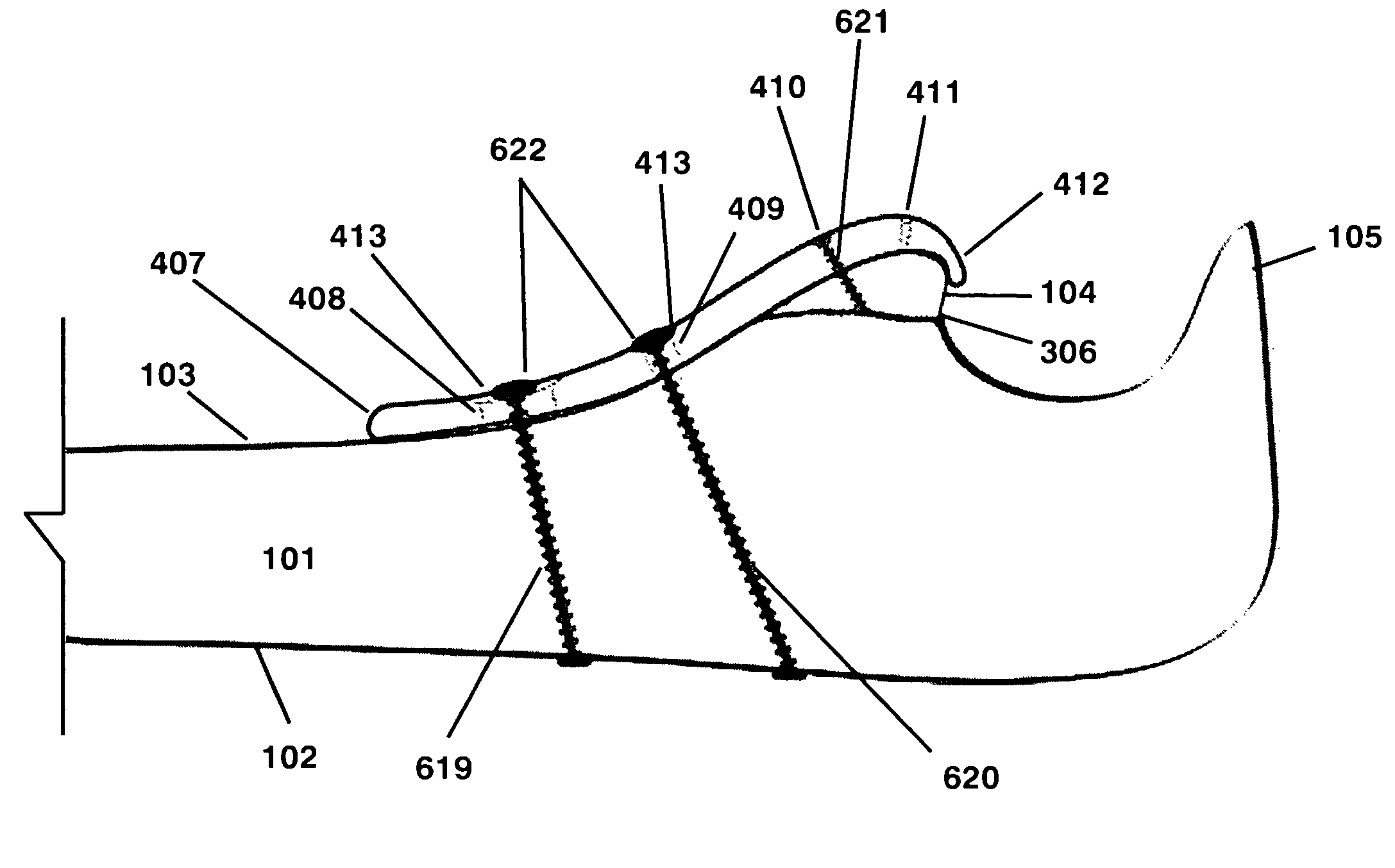

Embodiment Construction

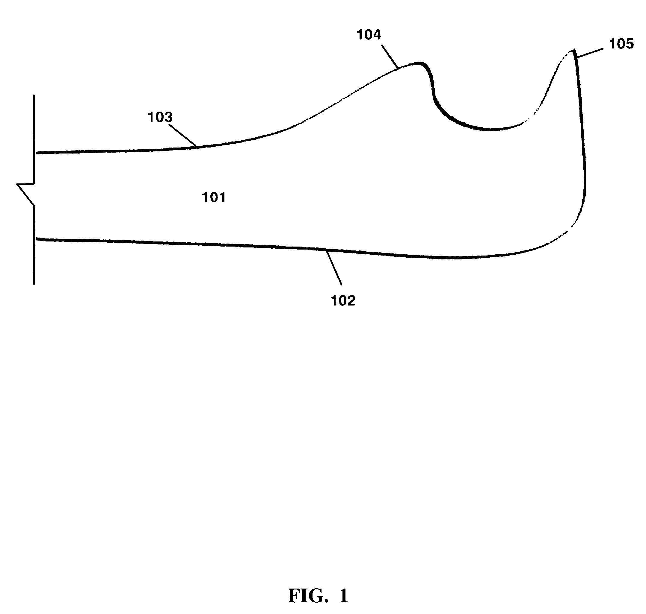
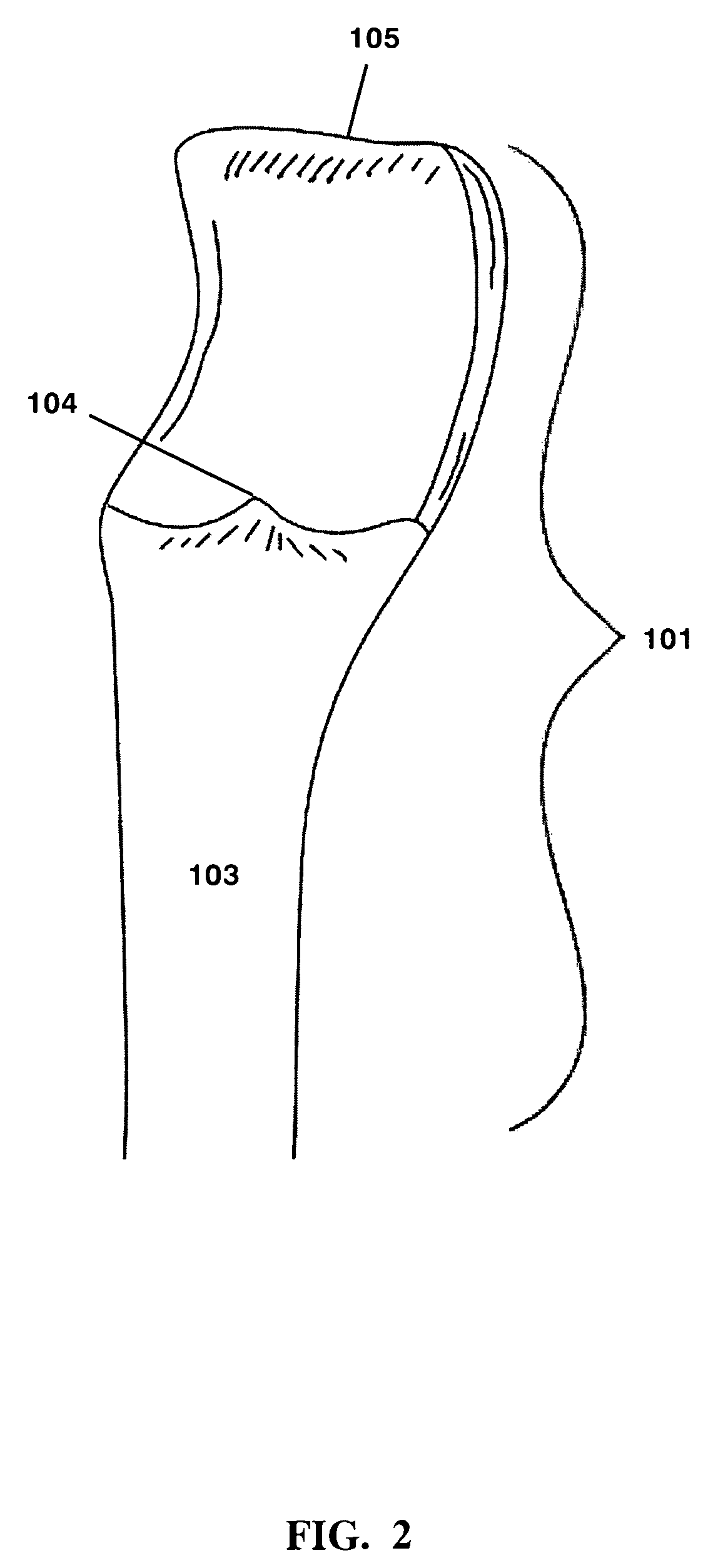
[0028]The present application is directed toward a specifically contoured bone plate and a system and method for ulna fixation. The bone plate, system and method may be used to treat for example, coronoid fractures of the proximal ulna.

[0029]In general, the bone plate is substantially rigid and specifically contoured to fit the anterior surface of the proximal ulna. The method generally includes securing the bone plate to the anterior surface of the proximal ulna as well as to the coronoid process or a bone graft relative to the fracture. The plate has surfaces that define openings through which screws and / or flexible devices such as suture and cable can pass. The method may also include forming at least one hole through the ulna, passing flexible device through an anchor and then passing the anchor through the hole in the ulna and through the bone plate from posterior to anterior and manipulating the anchor so that it resists passing back through the plate. The suture is then secur...


PUM


Abstract

An improved means for fixation of a fractured coronoid process of the proximal ulna. A substantially rigid plate is secured to the anterior aspect of the proximal ulna relative to a fracture of the coronoid process of the ulna. The plate contains a hook feature at the proximal aspect and is positioned so that it extends over the proximal / anterior aspect of the coronoid process relative to the fracture. The plate has surfaces that define a plurality of openings through which suture and / or screws can pass. The openings may contain a recess at a side of the plate opposite the ulna. At least one hole is formed in the ulna. At least one anchor may be secured to a flexible device, positioned at a side of the plate opposite the ulna, secured to another anchor on the posterior aspect of the ulna and the flexible device tensioned. At least one screw may be inserted through the plate and into the coronoid process or a bone fragment securing it to the plate.

Description

CROSS-REFERENCE TO RELATED APPLICATIONS[0001]The present application derives priority from U.S. provisional application No. 61 / 200,630, filed Dec. 2, 2008.BACKGROUND OF THE INVENTION[0002]1. Field of the invention[0003]The present invention relates broadly to surgical devices and methods for the internal fixation of fractured bones, and more particularly, to a system and method for fixation of a fractured coronoid process of the proximal ulna.[0004]2. Description of the Background[0005]Coronoid fractures of the proximal ulna may be associated with elbow instability. In certain cases surgical management of coronoid fractures may be indicated. The coronoid process of the ulna can be fractured when the human elbow experiences significant trauma. If there is associated ligamentous injury about the elbow, the joint will often become unstable and result in dislocation or subluxation. In this situation surgical fixation of coronoid fractures is necessary to stabilize the elbow. Because of ...

Claims


Application Information

Patent Timeline
Patent Type & Authority Patents(United States)
IPC IPC(8): A61B17/56A61B17/58A61B17/82A61F2/30
CPCA61B17/8061A61B17/683
Inventor GELFAND, JEFFREY
Owner GELFAND JEFFREY DR
Learn More