
Method for making a laminate

a technology of laminates and methods, applied in the field of laminate making methods, can solve the problems of increasing manufacturing costs, affecting the quality of laminates, and affecting the quality of laminates, and achieve the effect of making laminates continuously and efficiently

Inactive Publication Date: 2013-05-14
XXENTRIA TECH MATERIALS CO LTD
View PDF5 Cites 0 Cited by
  • Summary
  • Abstract
  • Description
  • Claims
  • Application Information

AI Technical Summary

Benefits of technology

[0007]Therefore, the object of this invention is to provide a method that can continuously and efficiently make a laminate with a bent structure including upper and lower metal layers and a core layer.

Problems solved by technology

However, production of the aforesaid laminate 1 is not a continuous process.
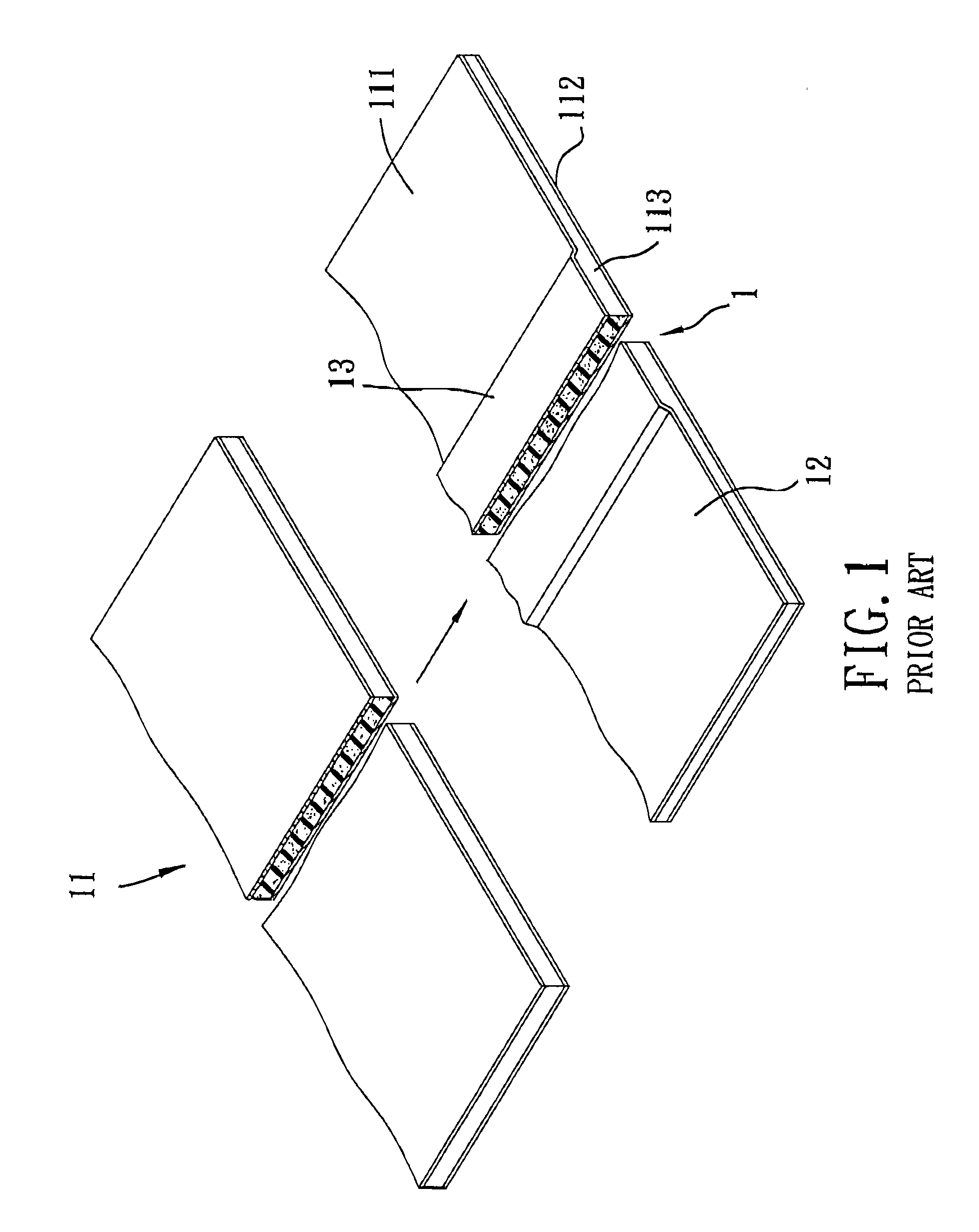
In particular, the flat laminates 11 thus formed have to be transferred to the pressing machine to form the laminate 1 with the bent structure, which is inefficient and which results in an increase in manufacturing costs.
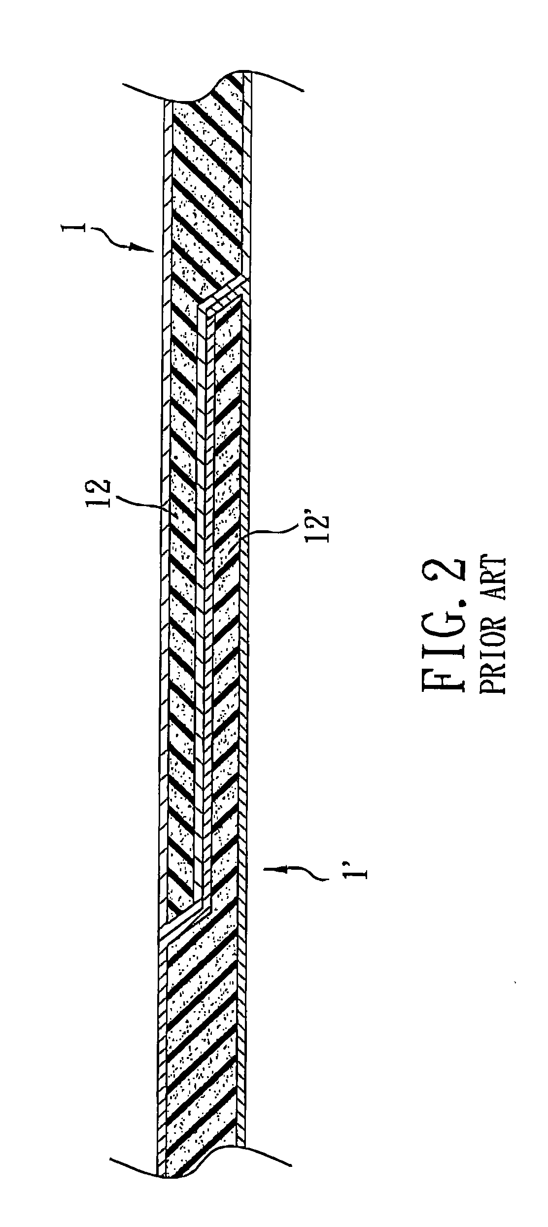
In addition, upon pressing, since the adhesive for adhering the upper and lower metal layers 111, 112 onto the core layer 113 have been cured, the strength of the adhesive is likely to be destroyed, thereby adversely affecting the adhesion property of the adhesive.

Method used


Image

  • Method for making a laminate
  • Method for making a laminate
  • Method for making a laminate

Examples


Embodiment Construction

[0016]The entire disclosure of the parent application, i.e., U.S. patent application Ser. No. 11 / 503,561, is incorporated herein by reference.

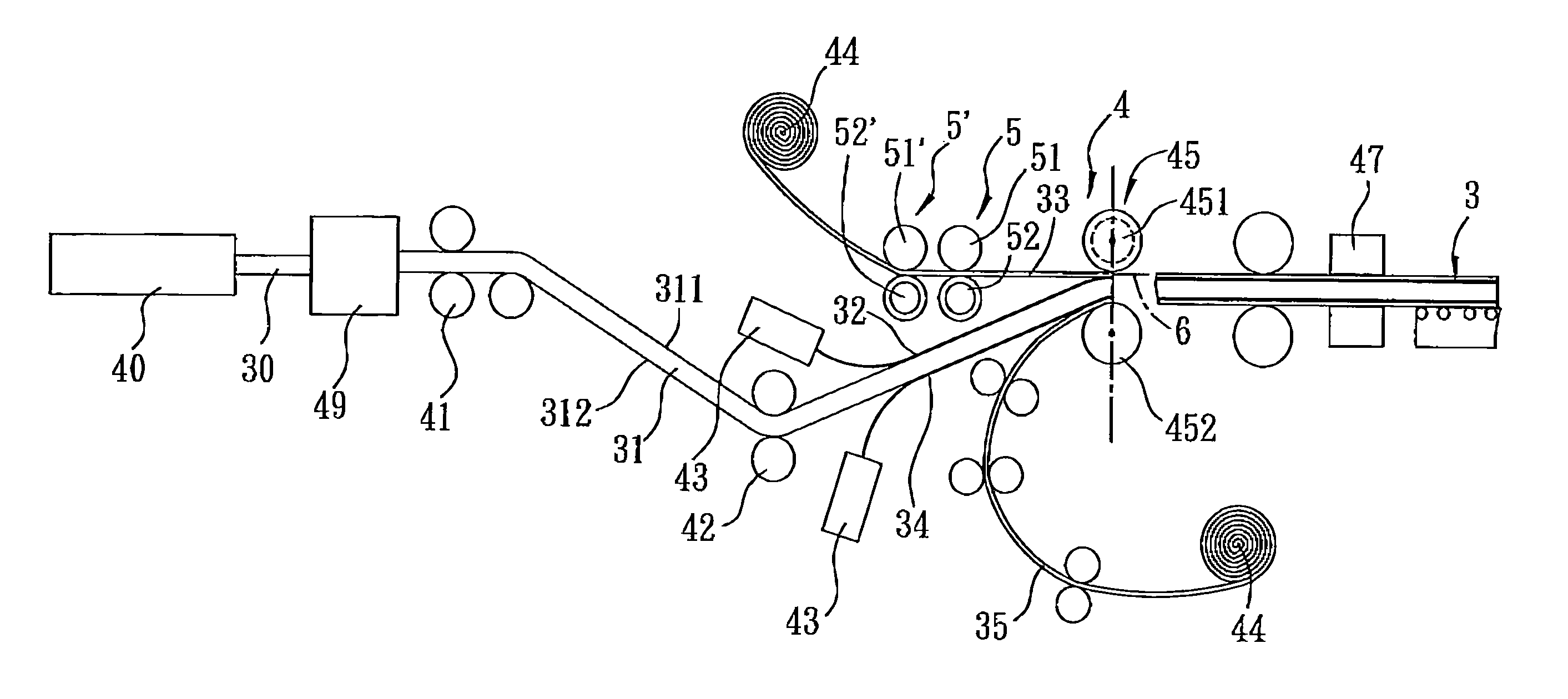
[0017]FIG. 3 illustrates the preferred embodiment of a method for making a laminate 3 according to the present invention and a system 4 used to perform the method of this invention. As shown in FIGS. 3 and 4, the laminate 3 includes a core layer 31 having an upper side 311 and a lower side 312, an upper metal layer 33 bonded adhesively on the upper side 311 of the core layer 31 by an adhesive layer 32, and a lower metal layer 35 bonded adhesively on the lower side 312 of the core layer 31 by an adhesive layer 34. At least one of the upper and lower metal layers 33, 35 is pressed to form a bent structure. In this embodiment, the upper metal layer 33 is formed with a raised bent structure, and the lower metal layer 35 is in a flat sheet form. Specifically, as shown in FIG. 4, in this embodiment, the upper metal layer 33 includes the raised bent ...


PUM

PropertyMeasurementUnit
angleaaaaaaaaaa
angleaaaaaaaaaa
angleaaaaaaaaaa

Abstract

A method for making a laminate includes: extruding a core layer, and advancing the same along a processing line; advancing upper and lower metal layers, and bending the upper metal layer to form a raised bent structure; laminating the upper and lower metal layers with the core layer by passing through a nip of a pair of laminating rollers, one of which has an embossing groove that is shaped to complement the raised bent structure and that permits the raised bent structure to pass therethrough; and embossing the core layer to protrude into the raised bent structure while the core layer and the upper and lower metal layers are passed through the nip. The upper metal layer is inclined with a tangent line that passes through the nip by an angle of less than 15 degrees when at a position immediately upstream of the nip.

Description

CROSS-REFERENCE TO RELATED APPLICATION[0001]This application is a continuation-in-part (CIP) of U.S. patent application Ser. No. 11 / 503,561, filed on Aug. 11, 2006 now abandoned, the entire disclosure of which is incorporated herein by reference.BACKGROUND OF THE INVENTION[0002]1. Field of the Invention[0003]This invention relates to a method for making a laminate, more particularly to a continuous method for making a laminate with a bent structure continuously.[0004]2. Description of the Related Art[0005]A laminate of a composite plate normally has a bent structure for enhancing the structural strength thereof. As shown in FIG. 1, a conventional laminate 1 with a bent structure includes upper and lower metal layers 111, 112, and a core layer 113 of a foam material sandwiched between the upper and lower metal layers 111, 112. The laminate 1 is produced by extruding the core layer 113, adhering the upper and lower metal layers 111, 112 onto the core layer 113 using an adhesive so as ...

Claims


Application Information

Patent Timeline
Patent Type & Authority Patents(United States)
IPC IPC(8): B29C53/04B29C47/02B29C48/07B29C48/08B29C48/15B29C48/21
CPCB29C43/305B29C44/326B29C66/83413B29C66/83415B32B38/0012B32B38/06Y10T156/1023B29C47/0021B29C47/02B29C59/04B29C65/5057B29C66/1122B29C66/1282B29C66/12861B29C66/14B29C66/43B29C66/45B29C66/723B29C66/742B29C2043/185B29K2105/04B29K2305/00B29L2009/003B32B37/1284B32B37/153B32B37/20B32B2305/022B32B2311/00B29C65/5021B29C65/4815B29C47/0019B29C47/0064B29C47/065B29C66/727Y10T156/101B29C43/46B29C66/71B29C66/72321B29C48/15B29C48/07B29C48/08B29C48/0021B29C48/21B29K2023/06B29K2023/10
Inventor CHENG, HSIEN-TECHENG, HSIEN-SUNG
Owner XXENTRIA TECH MATERIALS CO LTD
Learn More