Electromagnetic shielding sheet and method for manufacturing same

a technology of electromagnetic shielding and thin film, applied in the field of electromagnetic shielding sheet, can solve the problems of difficult formation of fine lines, difficulty in reducing the fineness of fine lines to increase transmittance, excessive surface electrical resistance of conductive thin film, etc., and achieves a high yield rate and continuous and efficient

Inactive Publication Date: 2005-10-20
DAI NIPPON PRINTING CO LTD
View PDF2 Cites 8 Cited by
  • Summary
  • Abstract
  • Description
  • Claims
  • Application Information

AI Technical Summary

Benefits of technology

[0026] The electromagnetic shielding sheet fabricating method according to the present invention can be continuously and efficiently carried out by existing equipment to fabricate a high-quality electromagnetic shielding sheet at a high yield rate.

Problems solved by technology

While the deposited conductive thin film of the metal or the metal oxide is formed not excessively thick to meet the required transparency, such as a thickness in the range of several hundreds to 2000 Å, the conductive thin film has an excessively high surface electrical resistance and is unsatisfactory in electromagnetic shielding ability.
The electromagnetic shielding sheet provided with a mesh structure having fine lines has high electromagnetic shielding ability, but is subject to limitations on reducing the fineness of the fine lines to increase transmittance.
Such fine lines are difficult to form.
Such thick conductive fibers are visible and deteriorate the visibility of displayed images.
The lines of the conductive resin have wide widths on the order of 100 μm due to limited printing accuracy.
Such wide lines deteriorate the visibility of displayed images.
However, the density of the black metal meshed frames (lines) of those electromagnetic sheets formed by these prior art methods is low, and the visibility of images displayed by displays provided with these electromagnetic shielding sheets is unsatisfactory.

Method used


Image

  • Electromagnetic shielding sheet and method for manufacturing same
  • Electromagnetic shielding sheet and method for manufacturing same
  • Electromagnetic shielding sheet and method for manufacturing same

Examples


example 1

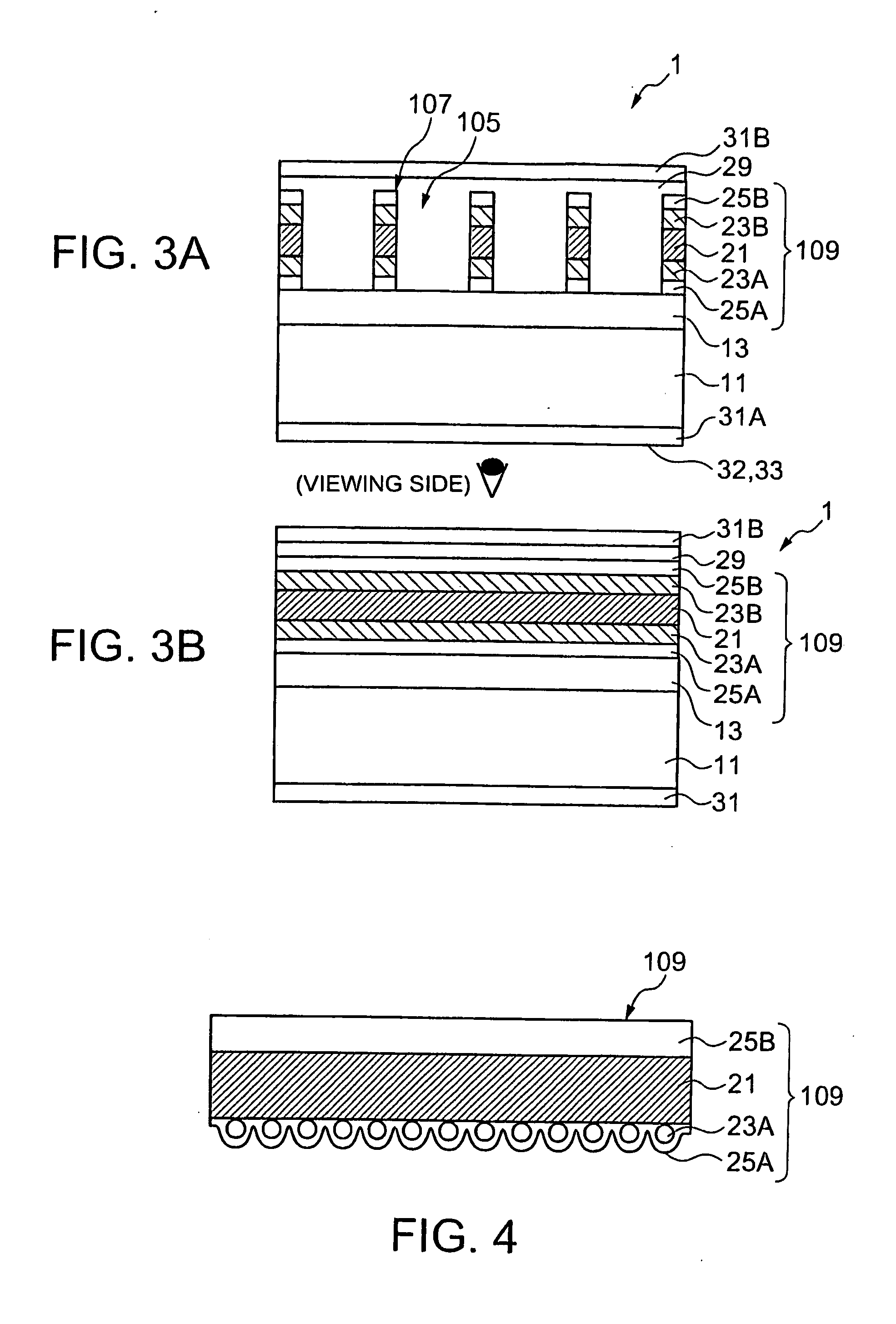
[0140] A conductive structure was formed by subjecting a 10 μm thick electrolytic Cu foil, which serves as a metal layer 21, to a cathodic electrodeposition process to form blackened layers 23A and 23B consisting of Cu—Co alloy particles having a mean particle size of 0.3 μm on the Cu foil, and a chromating treatment to form density-intensifying layers on the blackened layers 23A and 23B. A 100 μm thick transparent, biaxially oriented PET film A4300® (Toyobo) as a base was laminated to the surface treated by the chromating treatment of the Cu foil with a two-part polyurethane adhesive. A structure formed by laminating the PET film and the Cu foil was aged at 50° C. for three days. The two-part adhesive includes TAKERAKKU A-310® (polyol) (Takeda Yakuhin Kogyo) as an adhesive resin, and Hardener A-10® (isocyanate) (Takeda Yakuhin Kogyo) as a hardener. The two-part adhesive was spread in a 4 μm thick film in a dry state.

[0141] The structure formed in a continuous laminated film was ma...

example 2

[0150] Electromagnetic shielding sheets in Example 2 were fabricated by the steps of coating the surfaces of the mesh structures of the electromagnetic shielding sheets in Example 1 with a film of a flattening composition, laminating a 50 μm thick SP-PET20-BU® (Tosero), i.e., a PET film having a surface having a release characteristic, to the surface of the film of the flattening composition, exposing the thus coated electromagnetic shielding sheets to radiation of an intensity of 200 mj / cm2 (in terms of 365 nm) emitted by a high-pressure mercury lamp, and removing the SP-PET20-BU. The electromagnetic shielding sheets in Example 2 had abilities similar to those of the electromagnetic shielding sheets in Example 1.

[0151] The flattening composition was prepared by mixing 20 parts by mass of N-vinyl-2-pyrrolidone, 25 parts by mass dicyclopentenyl acrylate, 52 parts by mass oligoester acrylate (M-8060®, To a Gosei), and 3 parts by mass 1-hydroxycyclohexyl phenylketone (IRUGACURE 184, c...

example 3

[0152] Electromagnetic shielding sheets in Example 3 were fabricated similarly to those in Example 2, except that the electromagnetic shielding sheets in Example 3 had a flattening layer formed of a material prepared by adding one part by mass thiol-nickel complex, i.e., a near-infrared absorbing agent. The electromagnetic shielding sheets in Example 3 had abilities similar to those of the electromagnetic shielding sheets in Example 1, and an effect on improving the visibility of displayed images higher than that of Example 1.


PUM

PropertyMeasurementUnit
wavelengthsaaaaaaaaaa

Abstract

Blackened layers 23A and 23B are formed by depositing Cu—Co alloy particles on the surfaces of a metal layer 21. The metal layer 21 coated with the blackened layers 23A and 23B of the Cu—Co alloy particles is subjected to a chromating process to form density-intensifying layers 25A and 25B on the blackened layers 23A and 23B. A base 11 is laminated to the density-intensifying layer 25A or 25B. A conductive structure 109 consisting of the meal layer 21, the blackened layers 23A and 23B, and the density-intensifying layers 25A and 25B is processed by a photolithographic process to complete an electromagnetic shielding sheet 1 having a mesh conductive structure.

Description

TECHNICAL FIELD [0001] The present invention relates to an electromagnetic shielding sheet and a method of fabricating the same. More specifically, the present invention relates to an electromagnetic shielding sheet provided with a meshed, thin metal foil (thin film), intended to be disposed in front of a display, such as a cathode-ray tube (CRT) or a plasma display panel (PDP), to shield electromagnetic radiation generated by the display, and capable of enabling the satisfactory visual recognition of images displayed by the display. BACKGROUND ART [0002] Summary of Techniques [0003] Problems attributable to electromagnetic inference (EMI) have increased with the recent functional progress and spread of electric and electronic devices. Electromagnetic noise is classified roughly into conducted noise and radiated noise. Methods of preventing problems due to conducted noise filter conducted noise with a noise filter. Methods of preventing problems due to radiated noise use a metal cas...

Claims


Application Information

Patent Timeline
Patent Type & Authority Applications(United States)
IPC IPC(8): H05K9/00
CPCH05K9/0096Y10T428/25Y10T428/256Y10T442/109Y10T442/11Y10T442/112G09F9/00H05K9/00
Inventor KOJIMA, HIROSHI
Owner DAI NIPPON PRINTING CO LTD
Why Eureka
Try Eureka