Energy assisted magnetic recording head having laser integrated mounted to slider

a technology of laser integrated and magnetic recording head, which is applied in the direction of data recording, combination recording, instruments, etc., can solve the problems of adversely affecting the performance and reliability of laser diodes, other components, and failure to adequately dissipate heat generated

Active Publication Date: 2013-05-14
WESTERN DIGITAL TECH INC
View PDF39 Cites 43 Cited by
  • Summary
  • Abstract
  • Description
  • Claims
  • Application Information

AI Technical Summary

Problems solved by technology

Failure to adequately dissipate heat generated by the laser diode 30 may adversely affect performance and reliability of the laser diode 30, as well as other components of the EAMR disk drive 10.

Method used


Image

  • Energy assisted magnetic recording head having laser integrated mounted to slider
  • Energy assisted magnetic recording head having laser integrated mounted to slider
  • Energy assisted magnetic recording head having laser integrated mounted to slider

Examples


Embodiment Construction

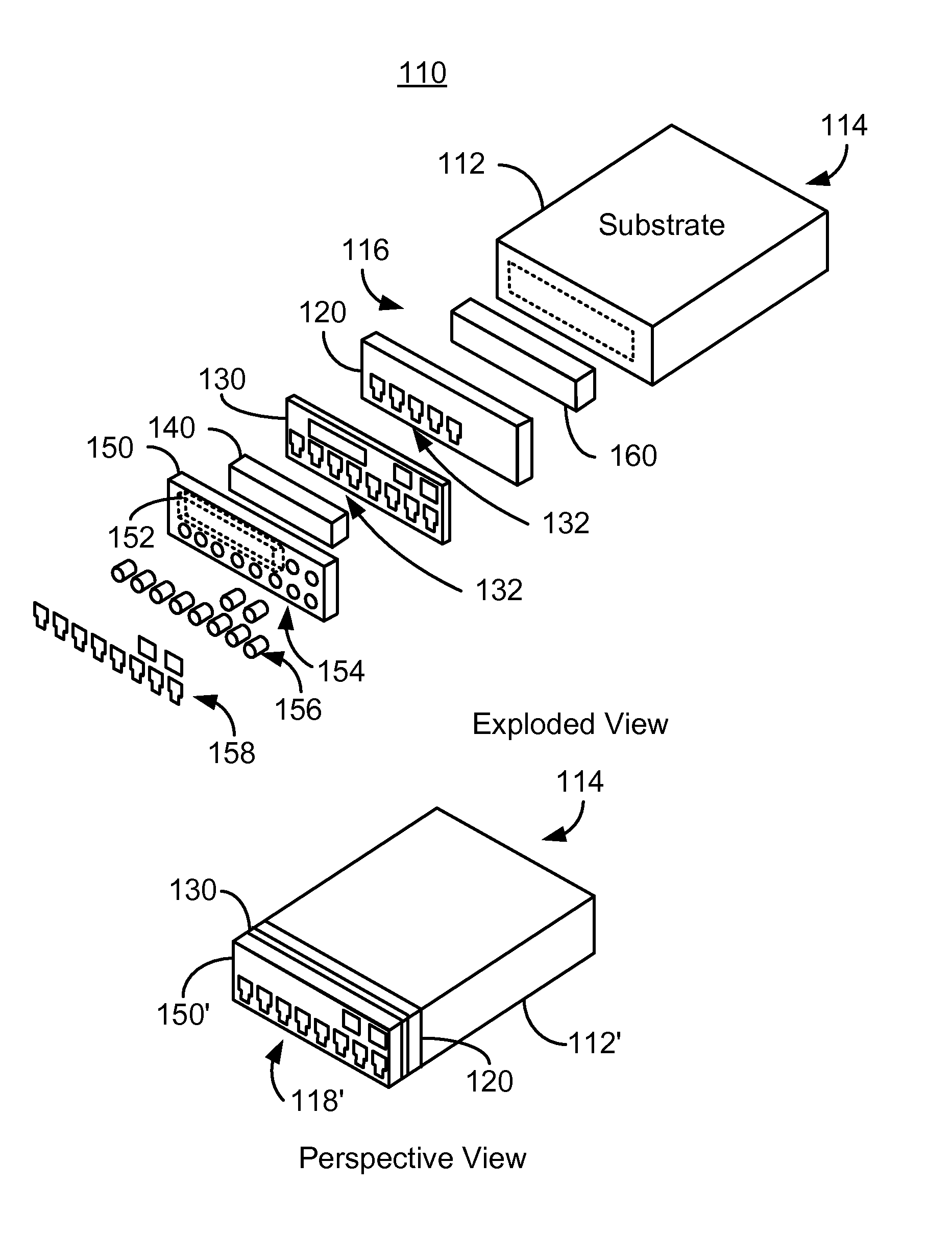
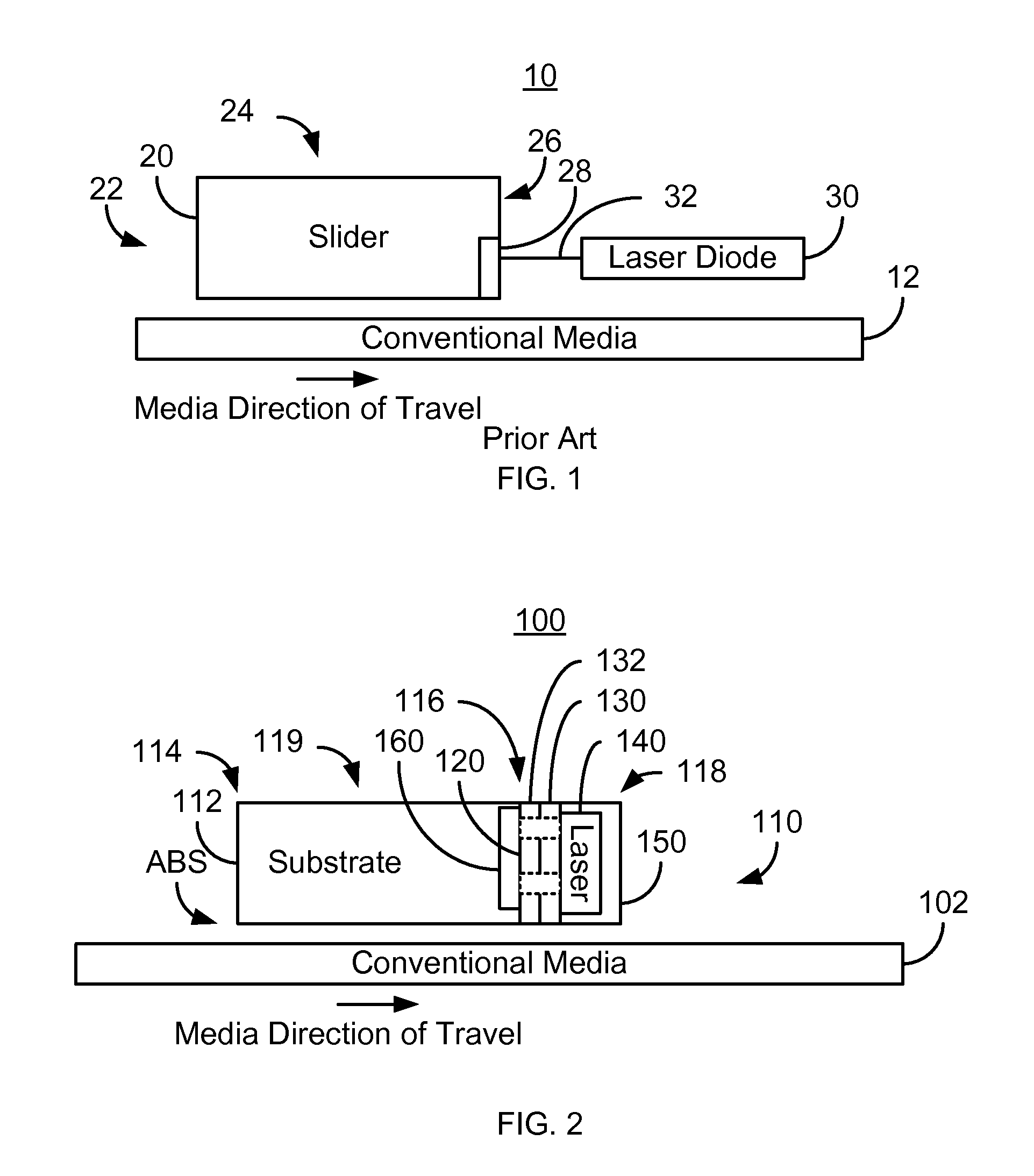
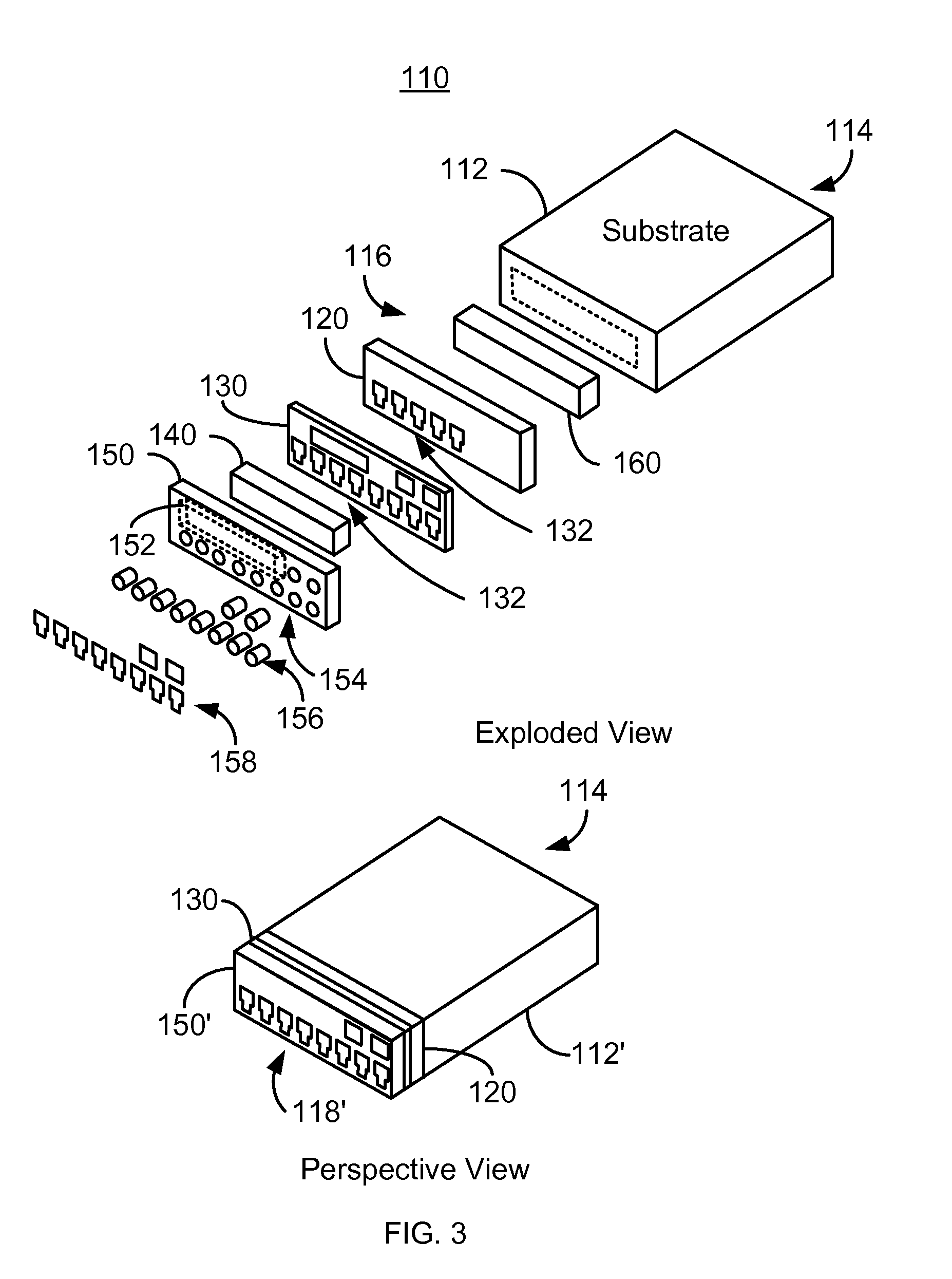
[0019]FIG. 2 depicts an exemplary embodiment of an EAMR disk drive 100 including an EAMR head 110. FIG. 3 depicts an EAMR head 110 used in the disk drive 100. FIG. 2 is a side view of the disk drive 100. FIG. 3 depicts exploded and perspective views of the EAMR head 110. For clarity, FIGS. 2-3 are not to scale. For simplicity not all portions of the EAMR disk drive 100 and EAMR head 110 are shown. In addition, although the disk drive 100 and EAMR head 110 are depicted in the context of particular components other and / or different components may be used. Further, the arrangement of components may vary in different embodiments.

[0020]The EAMR disk drive 100 includes a media 102 and an EAMR head 110, also termed a slider. The EAMR head 110 includes a substrate 112, a device layer 120, an overcoat layer 130, a laser 140, an optional capping layer 150, and optional heat spreader 160. The head 110 has a slider leading edge 114 and a trailing edge 118. The substrate 112 has a leading edge 1...


PUM

PropertyMeasurementUnit
thickaaaaaaaaaa
thickaaaaaaaaaa
thickaaaaaaaaaa

Abstract

A method and system for providing energy assisted magnetic recording (EAMR) heads are described. The method and system include providing a substrate, at least one EAMR transducer, an overcoat layer and at least one laser. The substrate has a leading edge and a substrate trailing edge. The EAMR transducer(s) reside in a device layer and on the substrate trailing edge. The overcoat layer includes a plurality of contacts. The device layer is between the overcoat layer and the substrate trailing edge. The laser(s) provide energy to the EAMR transducer. The overcoat layer is between the substrate trailing edge and the laser(s). The laser(s) are electrically coupled to at least a first portion of the contacts. The contacts provide thermal connection through the overcoat layer and the device layer. At least a second portion of the contacts is electrically insulated from the substrate.

Description

BACKGROUND[0001]FIG. 1 depicts a side view of portion of a conventional energy assisted magnetic recording (EAMR) disk drive 10. The conventional EAMR disk drive 10 includes a recording media 12, a conventional slider 20, and a conventional laser diode 30 that are typically attached to a suspension (not shown). The conventional slider 20 has a leading edge 22, a trailing edge 26, and a back side 24. Although termed “edges”, the leading edge 22 and trailing edge 26 are surfaces of the slider 20. The leading edge 22 and trailing edge 26 are so termed because of the direction the conventional media 12 travels with respect to the EAMR transducer 28. Other components that may be part of the conventional EAMR disk drive 10 are not shown. The conventional slider 20 is typically attached to the suspension at its back side 24. A conventional EAMR transducer 28 is coupled with the slider 20.[0002]The laser diode 30 is coupled in proximity to the EAMR transducer 28 on the trailing edge 26 of t...

Claims


Application Information

Patent Timeline
Patent Type & Authority Patents(United States)
IPC IPC(8): G11B11/00
CPCG11B5/105G11B5/6088G11B2005/0021G11B5/02G11B5/127G11B5/314
Inventor WANG, LEILEE, SHINGYAN, WENTAO
Owner WESTERN DIGITAL TECH INC
Why Eureka
Try Eureka