Flow reservoir for a paint spray gun

a technology of flow reservoir and paint spray gun, which is applied in the direction of spray nozzle, liquid spraying apparatus, spraying apparatus, etc., can solve the problems of high cost, inability to directly attach the container cover with the cylindrical attachment part, and relatively complicated production of such flow reservoir with attachment parts manufactured separately and then connected to the container, etc., to achieve the effect of fast and easy assembly, economic manufacturing

Active Publication Date: 2013-05-21
SATA GMBH & CO KG
View PDF21 Cites 58 Cited by
  • Summary
  • Abstract
  • Description
  • Claims
  • Application Information

AI Technical Summary

Benefits of technology

[0004]The task of the invention is to create a flow reservoir of the type mentioned in the introduction, which can be manufactured economically, and which can be attached quickly and easily to a paint spray gun without an additional adapter.
[0006]One essential advantage of the flow reservoir according to the invention is that it consists of two parts that are easy to manufacture. The flow reservoir can be attached easily and quickly to the paint spray gun without an additional adapter by means of the screw-wedge element located on the cover, and can also be removed again from this gun quickly. The flow reservoir, which can be produced economically, can be filled easily and can be used either as a one-time reservoir, as a reusable container, or also as a storage container for leftover paints or lacquers.

Problems solved by technology

However, the production of such flow reservoirs with attachment parts manufactured separately and then connected to the container is relatively complicated, and is associated with correspondingly high costs.
In these known flow reservoirs, however, the container cover with the cylindrical attachment part cannot be attached directly to the paint spray gun.

Method used


Image

  • Flow reservoir for a paint spray gun
  • Flow reservoir for a paint spray gun
  • Flow reservoir for a paint spray gun

Examples


Embodiment Construction

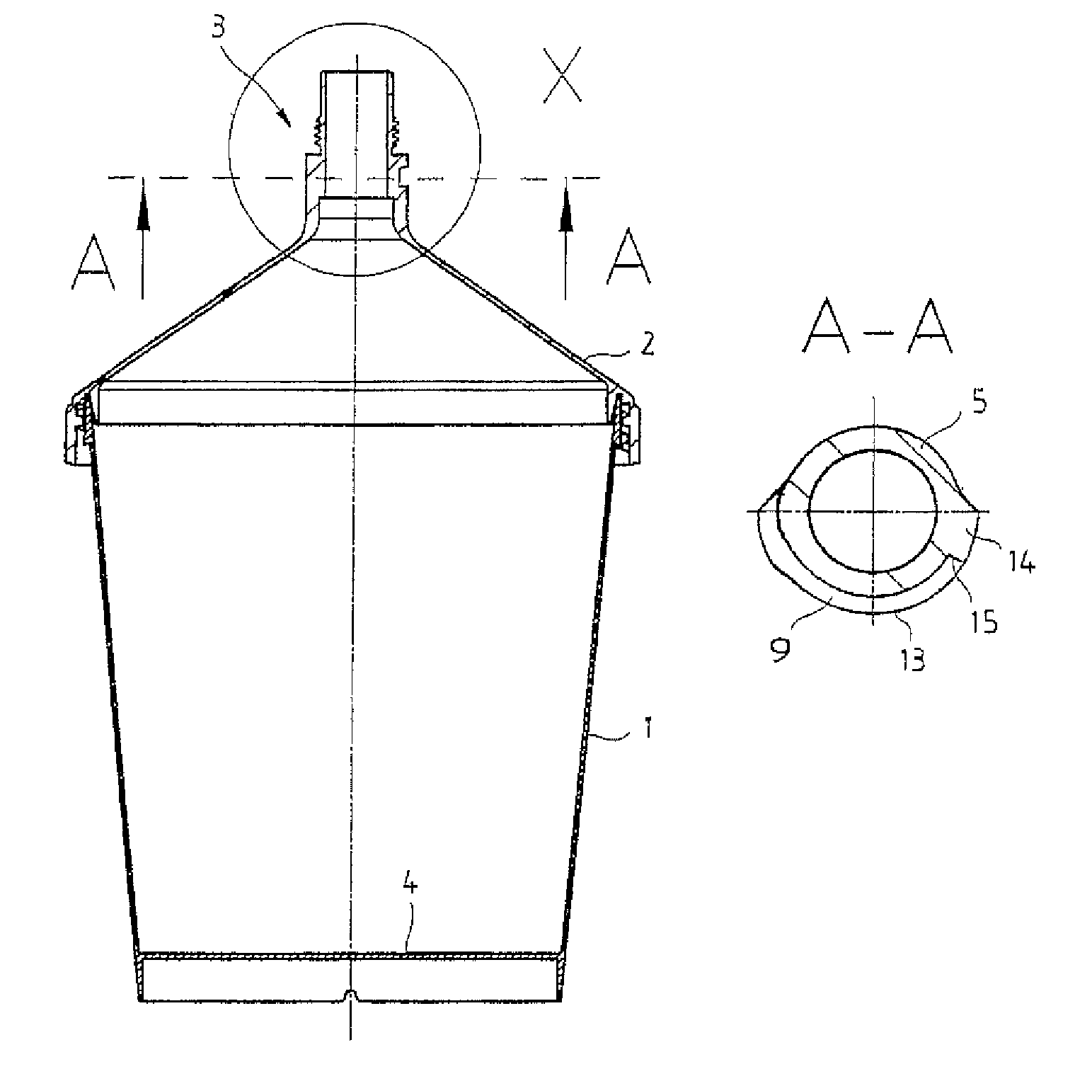
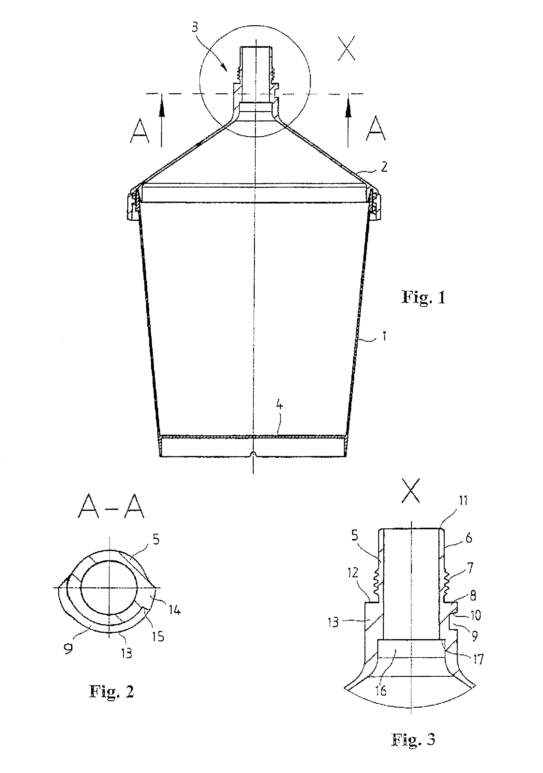
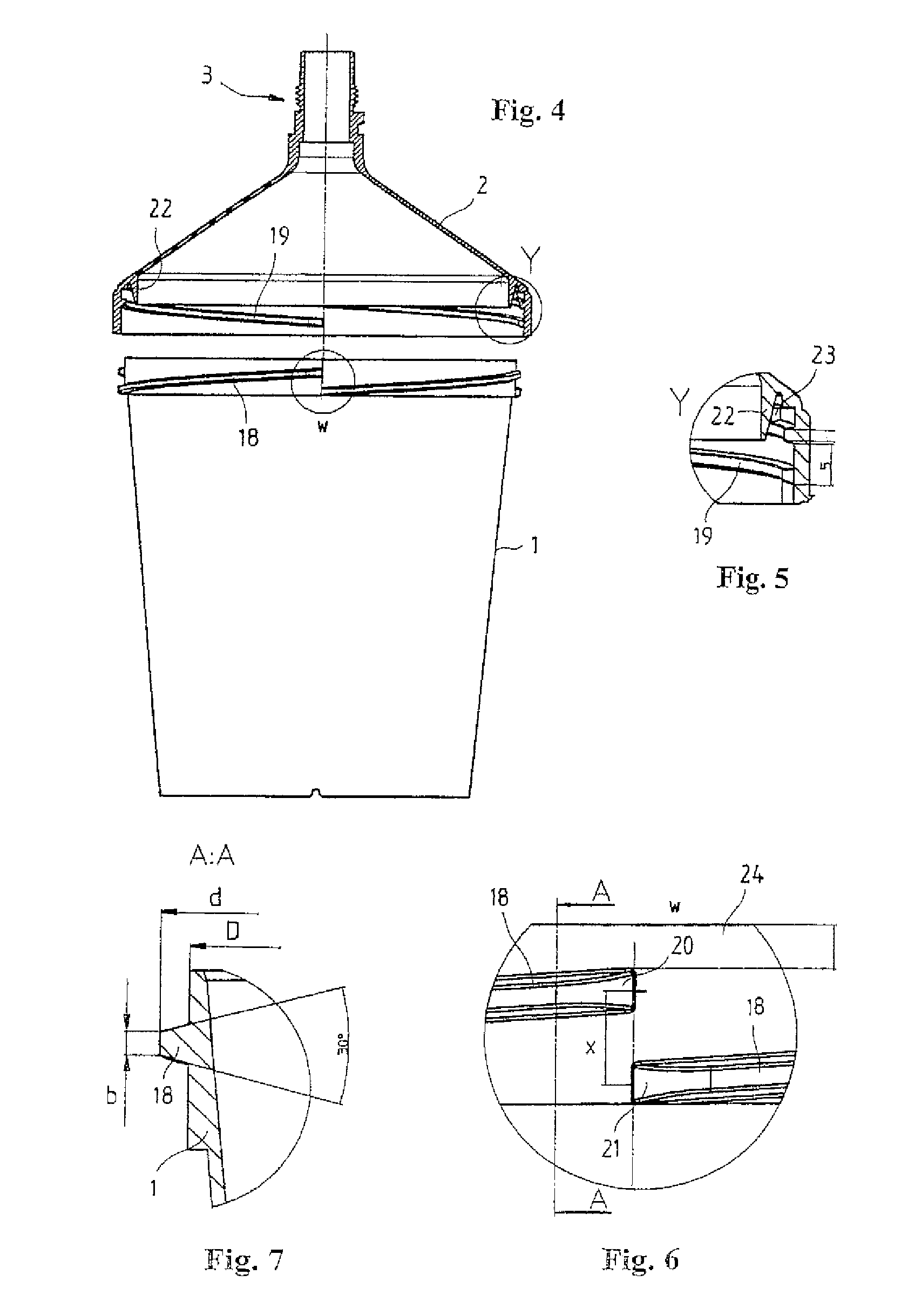
[0017]The flow reservoir shown in FIG. 1 for a paint spray gun contains a bowl-shaped container 1 and a cover 2 that can be set on this container. An attachment part 3 for detachable fastening of the flow reservoir onto a paint spray gun is formed on the cover. Both the container 1 and also the cover 2 with the formed attachment part 3 are preferably produced from plastic as injection-molded parts. The bowl-shaped container 1 is filled in the position shown with the cover 2 removed. Then the cover 2 can be put in place and inserted by its attachment part 3 into the attachment opening of an upside-down paint spray gun. To spray, the paint spray gun can then be inverted, so that the flow reservoir is located on the top side of the paint spray gun. To enable ventilation of the flow reservoir, e.g., a not-shown ventilation valve, which is provided on the floor 4 of the flow reservoir, can be opened, or an initially closed ventilation channel can be punctured with the help of a pin or th...


PUM


Abstract

The invention relates to a flow reservoir for a paint spray gun with a bowl-shaped container (1), a cover (2) that can be set on the container (1), and an attachment part (3) for direct fixing of the flow reservoir to the paint spray gun. The flow reservoir is distinguished in that the attachment part (3) consists of a connector (5) formed directly on the cover (2) with a screw-wedge element (8) for direct quick-connect attachment of the flow reservoir to the paint spray gun.

Description

FILED OF THE INVENTION[0001]The invention relates to a flow reservoir for a paint spray gun.BACKGROUND OF THE INVENTION[0002]Conventional flow reservoirs for paint spray guns typically have a bowl-shaped container, whose bottom side has an opening with an attachment part for detachable fastening of the container on the upper side of the paint spray gun. The attachment part typically consists of a connector that is inserted into the container floor and that has an external thread for screwing into a corresponding threaded opening on the upper side of the paint spray gun. The bowl-shaped container is usually closed on its upper side by a suitable cover, which should prevent undesired paint leakage. However, the production of such flow reservoirs with attachment parts manufactured separately and then connected to the container is relatively complicated, and is associated with correspondingly high costs.[0003]From WO 01 / 12337 A1, flow reservoirs are already known that include a bowl-sha...

Claims


Application Information

Patent Timeline
Patent Type & Authority Patents(United States)
IPC IPC(8): B05B7/30B05B7/24
CPCB05B7/2478B05B7/2408
Inventor SCHMON, EWALDDETTLAFF, PETER
Owner SATA GMBH & CO KG
Why Eureka
Try Eureka