Performance apparatus and electronic musical instrument

a performance apparatus and electronic technology, applied in the direction of instruments, electrophonic musical instruments, measurement devices, etc., can solve the problems of difficult for a player to change musical tones as he or she, and it is difficult to generate musical tones of the tone color desired by the player, so as to achieve the effect of easy change of musical tone elements including tone colors

Active Publication Date: 2013-05-21
CASIO COMPUTER CO LTD
View PDF15 Cites 13 Cited by
  • Summary
  • Abstract
  • Description
  • Claims
  • Application Information

AI Technical Summary

Benefits of technology

[0009]The present invention has an object to provide a performance apparatus and an electronic musical instrument, which allow the player to easily change musical tone elements including tone colors, as he or she desires.

Problems solved by technology

But in the performance apparatus disclosed in U.S. Pat. No. 5,058,480, generation of musical tones is simply controlled based on the acceleration sensor values of the stick-type member and therefore, the performance apparatus has a drawback that it is not easy for a player to change musical tones as he or she desires.
In the apparatus, as the kind of tone colors of musical tones to be generated increase, an angle range in which the stick-type member is swung to generate such tone color become narrower, and therefore it becomes harder to generate musical tones of a tone color desired by the player.

Method used


Image

  • Performance apparatus and electronic musical instrument
  • Performance apparatus and electronic musical instrument
  • Performance apparatus and electronic musical instrument

Examples


first embodiment

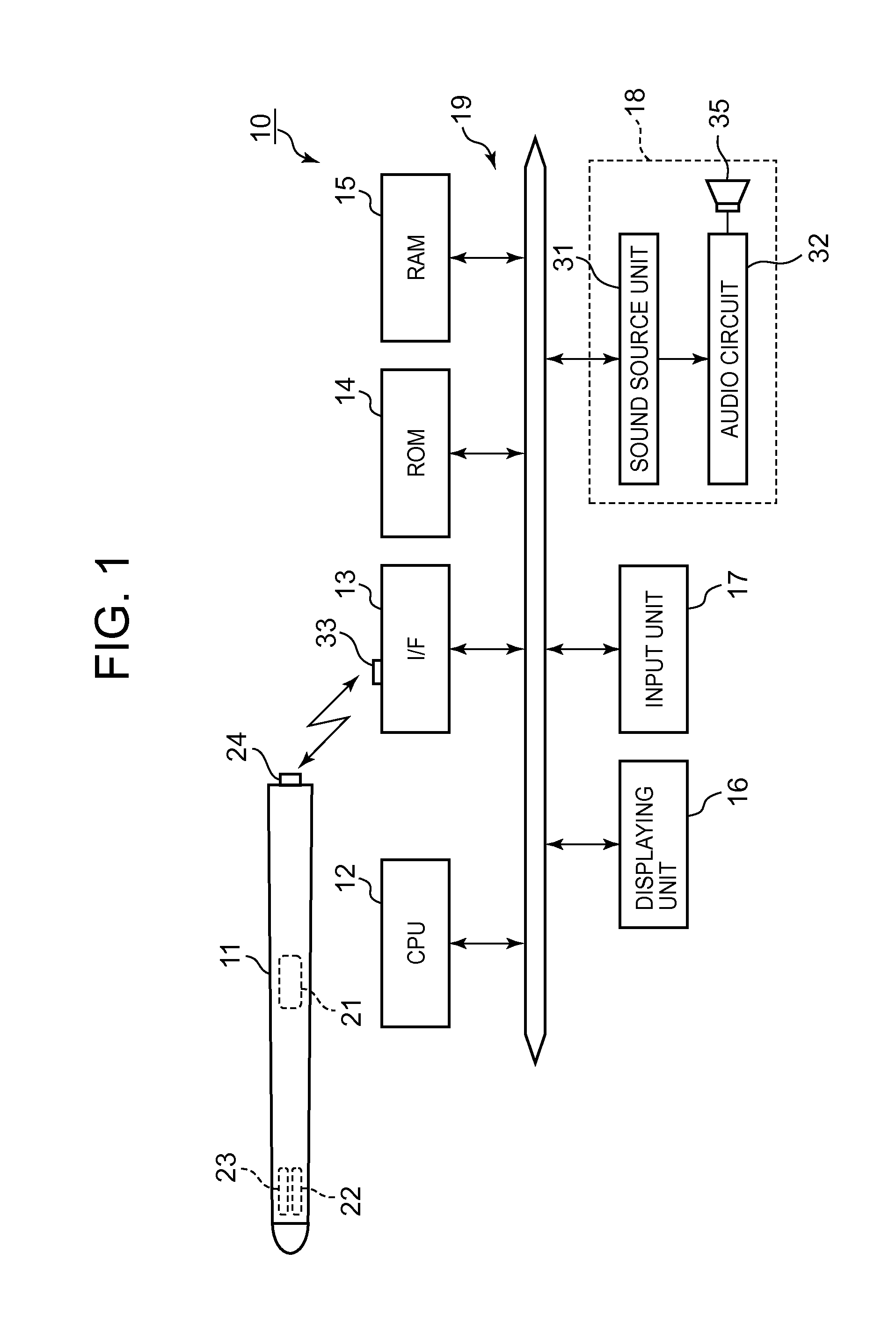
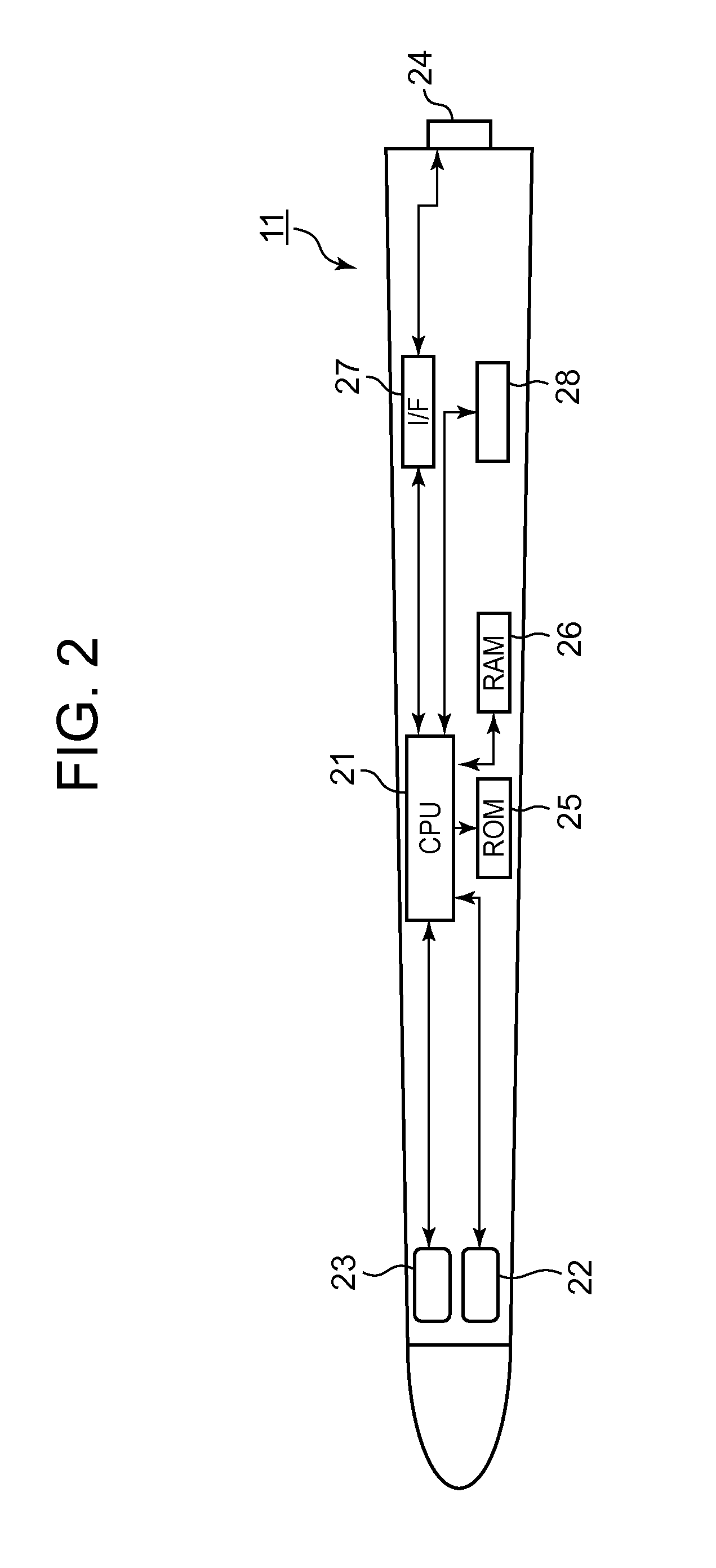
[0039]FIG. 2 is a block diagram of a configuration of the performance apparatus 11 in the invention. As shown in FIG. 2, the performance apparatus 11 is equipped with the geomagnetic sensor 22 and the acceleration sensor 23 in the head portion of the performance apparatus 11 opposite to its base portion. The portion where the geomagnetic sensor 22 to be mounted on is not limited to the head portion, but the geomagnetic sensor 22 may be mounted on the base portion. Taking the head of the performance apparatus 11 as the reference (that is, keeping eyes on the head of the performance apparatus 11), the player often swings the performance apparatus 11. Therefore, since it is taken into consideration that information of the head position of the performance apparatus 11 is obtained, it is preferable for the geomagnetic sensor 22 to be mounted on the head portion of the performance apparatus 11. It is also preferable to mount the acceleration sensor 23 in the head portion of the performanc...

second embodiment

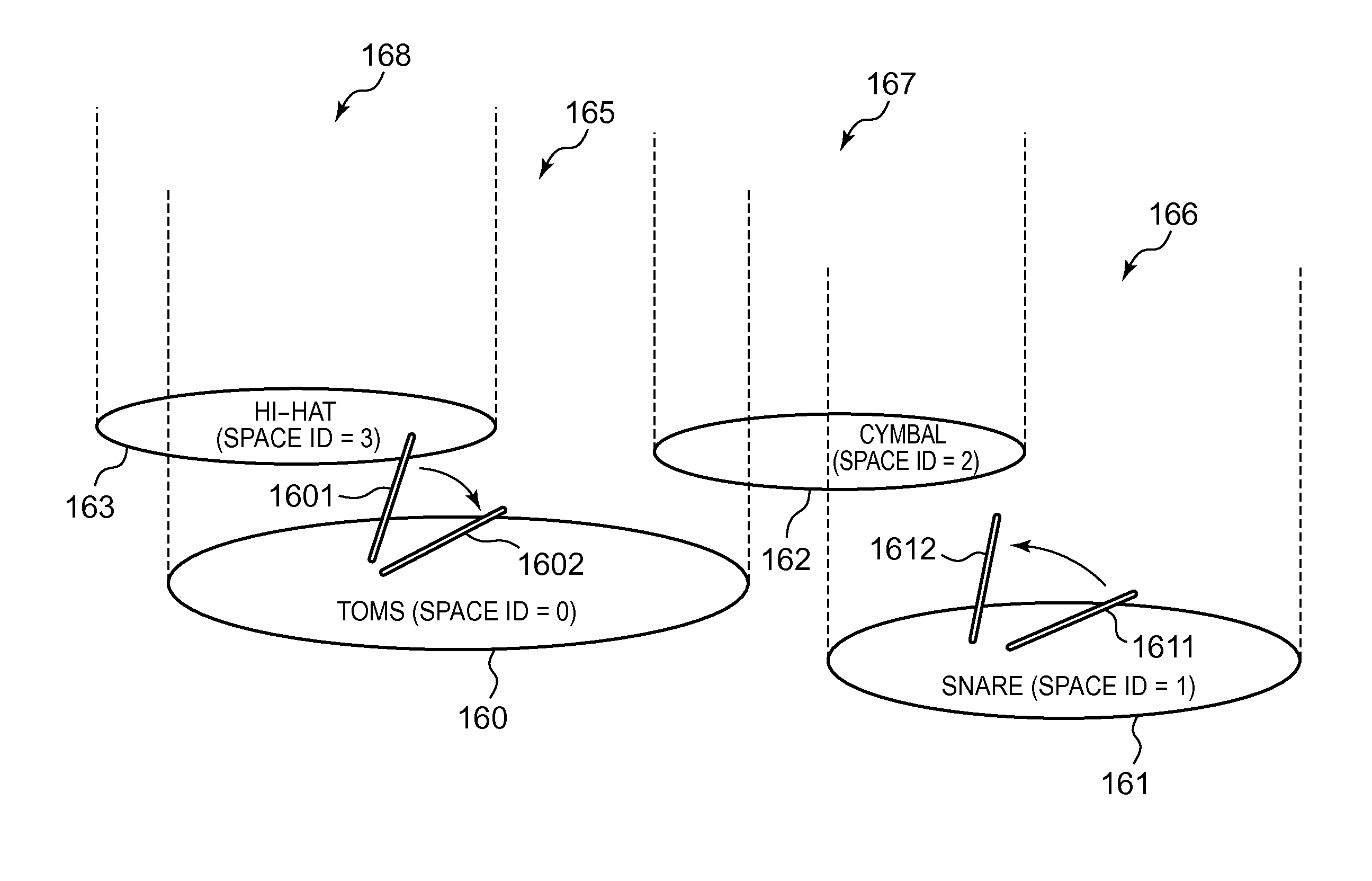
[0085]FIG. 14 is a flow chart of an example of the space setting process to be performed in the invention. CPU 21 of the performance apparatus 11 judges at step 1401 whether or not a center setting switch of the input unit 28 is kept on. When it is determined NO at step 1401, then the space setting process finishes. When it is determined YES at step 1401, CPU 21 judges at step 1402 whether or not the center setting switch has been turned on again. When it is determined YES at step 1402, CPU 21 reads position information from RAM 26, and stores in RAM 26 the read position information as position information (coordinate (xc, yc, zc)) of the central position C (step 1403).

[0086]When it is determined NO at step 1402, that is, when the center setting switch is kept on, or after the process at step 1403, CPU 21 judges at step 1404 whether or not the center setting switch has been turned off. When it is determined NO at step 1404, then the space setting process finishes. When it is determi...

fifth embodiment

[0114]FIG. 20 is a flow chart of an example of the sound-generation timing detecting process to be performed in the invention. The processes at steps 2001 to 2003 are performed substantially in the same manner as those at 901 to 903 in FIG. 9. When it is determined YES at step 2002, CPU 21 reads an acceleration sensor value (x-component, y-component, z-component) (step 2004) to calculate a sensor resultant value (step 2005). As described above, the sensor resultant value is given by the square root of the sum of the squares of the x-, y- and Z-components of the tri-axial acceleration sensor.

[0115]Then, CPU 21 judges at step 2006 whether or not the acceleration flag in RAM 26 is set to “0”. When it is determined YES at step 2006, CPU 21 judges at step 2007 whether or not the sensor resultant value is larger than a value of (1+a)G, where “a” is a positive fine constant. For example, if “a” is “0.05”, CPU 21 judges whether or not the sensor resultant value is larger than a value of 1.0...


PUM


Abstract

A performance apparatus 11 extends in its longitudinal direction to be held by a player with his or her hand. The performance apparatus 11 is provided with a geomagnetic sensor 22 and an acceleration sensor 23. At the time when the geomagnetic sensor and acceleration sensor determine that the performance apparatus 11 is kept within a sound generation space and has been moved by the player, CPU 21 gives an electronic musical instrument 19 an instruction to generate a musical tone of a tone color corresponding to the sound generation space. The sound generation spaces and corresponding tone colors are stored in a space / tone color table in RAM 26. Upon receipt of the instruction, the electronic musical instrument generates a musical tone of a tone color corresponding to the sound generation space.

Description

CROSS-REFERENCE TO RELATED APPLICATIONS[0001]The present application is based upon and claims the benefit of priority from prior Japanese Patent Application No. 2010-284229, filed Dec. 21, 2010, the entire contents of which are incorporated herein by reference.BACKGROUND OF THE INVENTION[0002]1. Field of the Invention[0003]The present invention relates to a performance apparatus and an electronic musical instrument, which generate musical tones, when held and swung by a player with his or her hand.[0004]2. Description of the Related Art[0005]An electronic musical instrument has been proposed, which is provided with an elongated member of a stick type with a sensor installed thereon, and generates musical tones when the sensor detects a movement of the elongated member. Particularly, in the electronic musical instrument, the elongated member of a stick type has a shape of a drumstick and is constructed so as to generate musical tones as if percussion instruments generate sounds in re...

Claims


Application Information

Patent Timeline
Patent Type & Authority Patents(United States)
IPC IPC(8): G10H1/32G10H3/00
CPCG10H1/0008G10H2220/185G10H2230/281G10H2220/401G10H2220/395
Inventor SAKAZAKI, NAOYUKI
Owner CASIO COMPUTER CO LTD
Why Eureka
Try Eureka