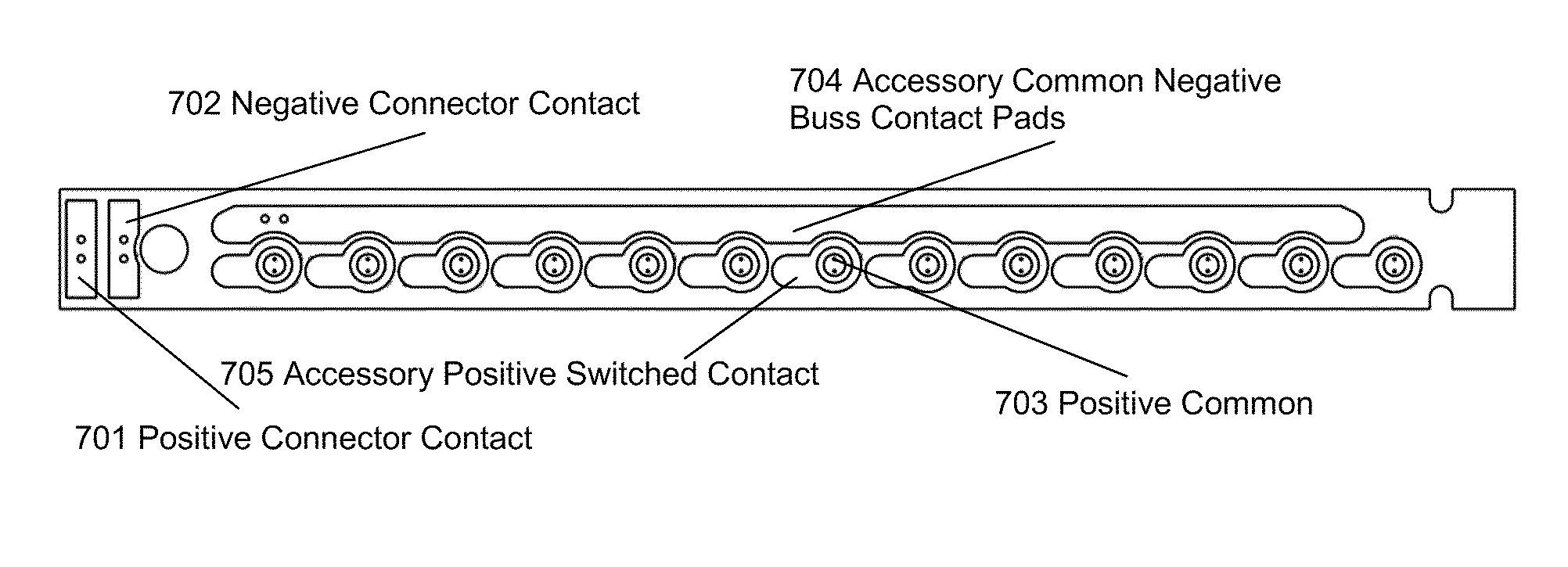
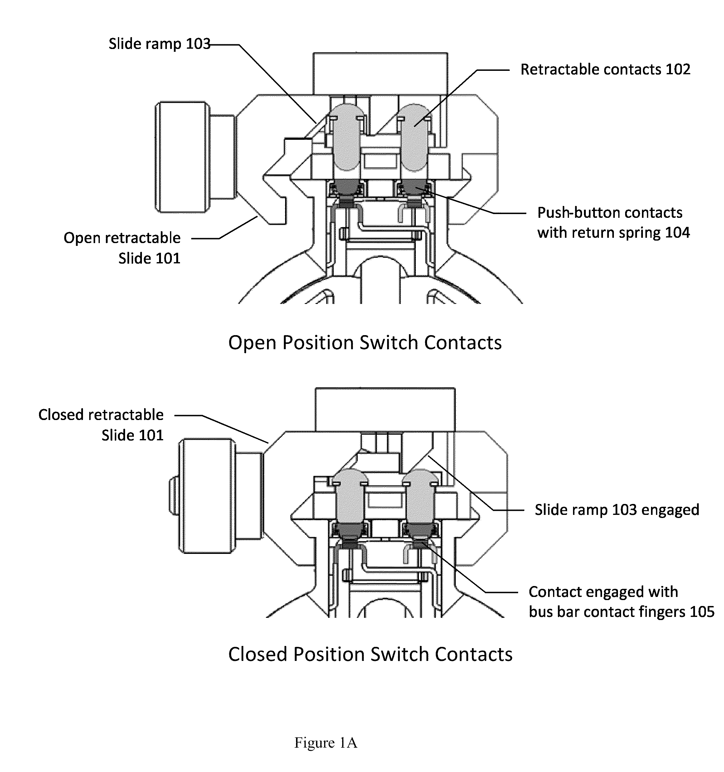
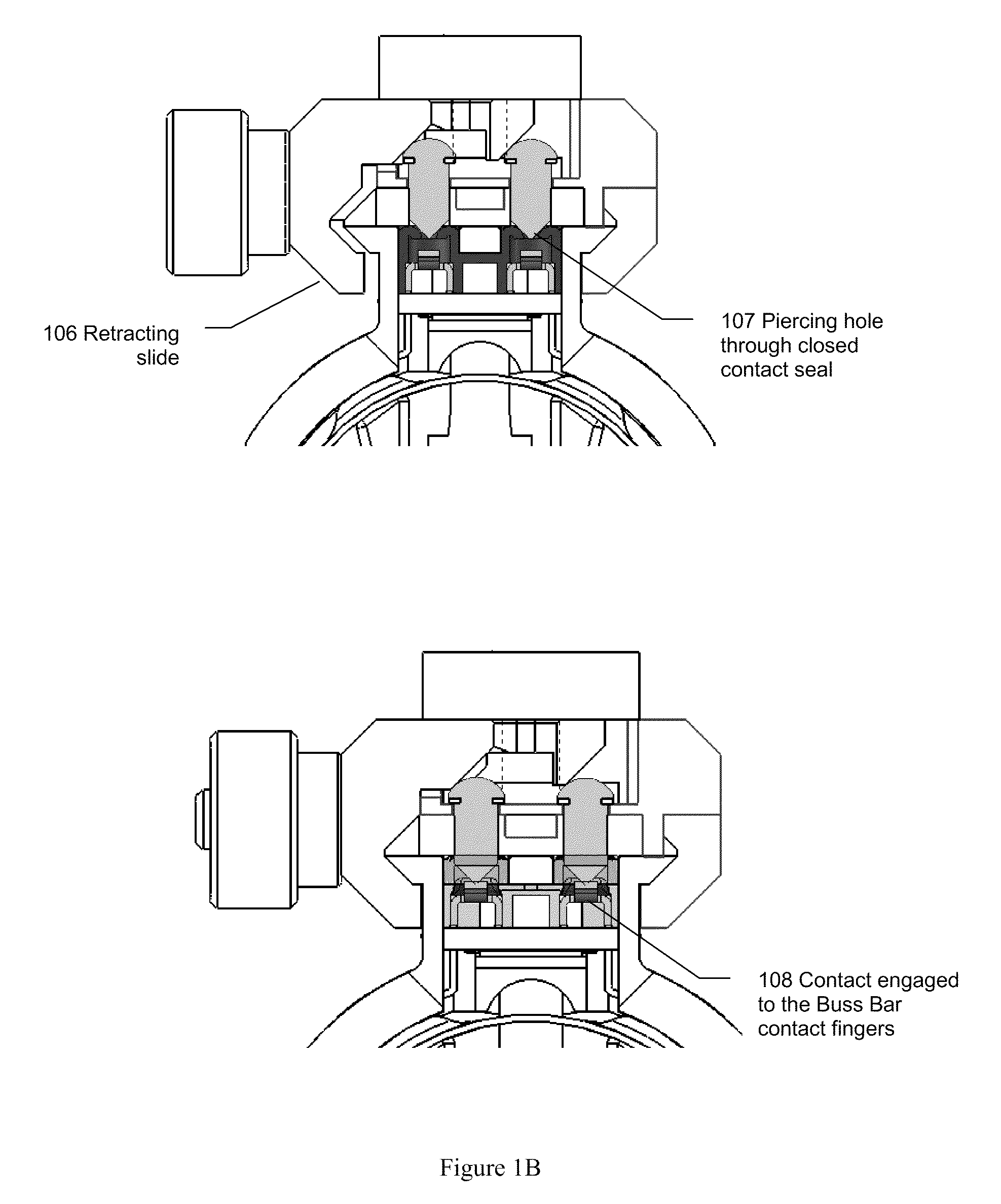
Rifle accessory rail, communication, and power transfer system-rail contacts

a technology of accessory rails and power transfer systems, applied in the field of weapons systems, can solve the problems of affecting the effectiveness of soldiers in the final stag

Active Publication Date: 2013-05-28
T WORX HLDG LLC
View PDF56 Cites 64 Cited by
  • Summary
  • Abstract
  • Description
  • Claims
  • Application Information

AI Technical Summary

Benefits of technology

[0005]It is an object of the present invention to obviate or mitigate at least one disadvantage of previous firearm accessory rails.

Problems solved by technology

The result is a heavy weapon and a heavier field load of batteries to accommodate the various accessories, which ultimately impacts the soldiers' effectiveness, particularly on longer missions.

Method used


Image

  • Rifle accessory rail, communication, and power transfer system-rail contacts
  • Rifle accessory rail, communication, and power transfer system-rail contacts
  • Rifle accessory rail, communication, and power transfer system-rail contacts

Examples


Embodiment Construction

[0033]For simplicity and illustrative purposes, the principles of the present invention are described by referring to various exemplary embodiments thereof. Although the preferred embodiments of the invention are particularly disclosed herein, one of ordinary skill in the art will readily recognize that the same principles are equally applicable to, and can be implicated in other compositions and methods, and that any such variation would be within such modifications that do not part from the scope of the present invention. Before explaining the disclosed embodiments of the present invention in detail, it is to be understood that the invention is not limited in its application to the details of any particular embodiment shown, since of course the invention is capable of other embodiments. The terminology used herein is for the purpose of description and not of limitation. Further, although certain methods are described with reference to certain steps that are presented herein in cer...


PUM


Abstract

The present invention is related to weapons systems. In particular, the present invention is directed to accessory attachment systems for rifles and small arms weapons that enable attached accessory devices to draw power from a central power source and communicate with the user and / or other devices.

Description

CROSS-REFERENCE TO RELATED APPLICATIONS[0001]This Patent Application claims the benefit of U.S. Provisional Patent Application Ser. No. 61 / 145,222, filed on Jan. 16, 2009. This application also is related to the US Patent Applications filed on the same date as the present application. Jan. 19. 2010. titled “Rifle Accessory Rail, Communication and Power Transfer System—Battery Pack”, which is U.S. patent application Ser. No. 12 / 689,438; “Accessory Mount for Rifle Accessory Rail Communication and Power Transfer System—Accessory Attachment”, which is U.S. patent application Ser. No. 12 / 689,436; “Rifle Accessory Rail, Communication, and Power Transfer System”, which is U.S. patent application Ser. No. 12 / 689,430, “Rifle Accessory Rail Communication and Power Transfer System—Communication”, which is U.S. patent application Ser. No. 12 / 689,437; and “Rifle Accessory Rail Communication and Power Transfer System—Power Distribution”, which is U.S. patent application Ser. No. 12 / 689,439, and i...

Claims


Application Information

Patent Timeline
Patent Type & Authority Patents(United States)
IPC IPC(8): F41C23/00
CPCF41G1/387F41G11/003
Inventor CABAHUG, ERIC F.DODD, JAMES S.TAPIA, HECTORSCHROEDER, JOHNTILTON, JAYMCLAUGHLIN, DONFELDMAN, BEN
Owner T WORX HLDG LLC
Why Eureka
Try Eureka