

Cutting guide board
a guide board and cutting technology, applied in the direction of cross-cut reciprocating saws, sawing apparatus, metal-working hand tools, etc., can solve the problems of inconvenient insertion of knife thrust, lack of left-right control, similar awkwardness, etc., to achieve convenient insertion, less expensive, and easy insertion
- Summary
- Abstract
- Description
- Claims
- Application Information
AI Technical Summary
Benefits of technology
Problems solved by technology
Method used
Image

Examples
example
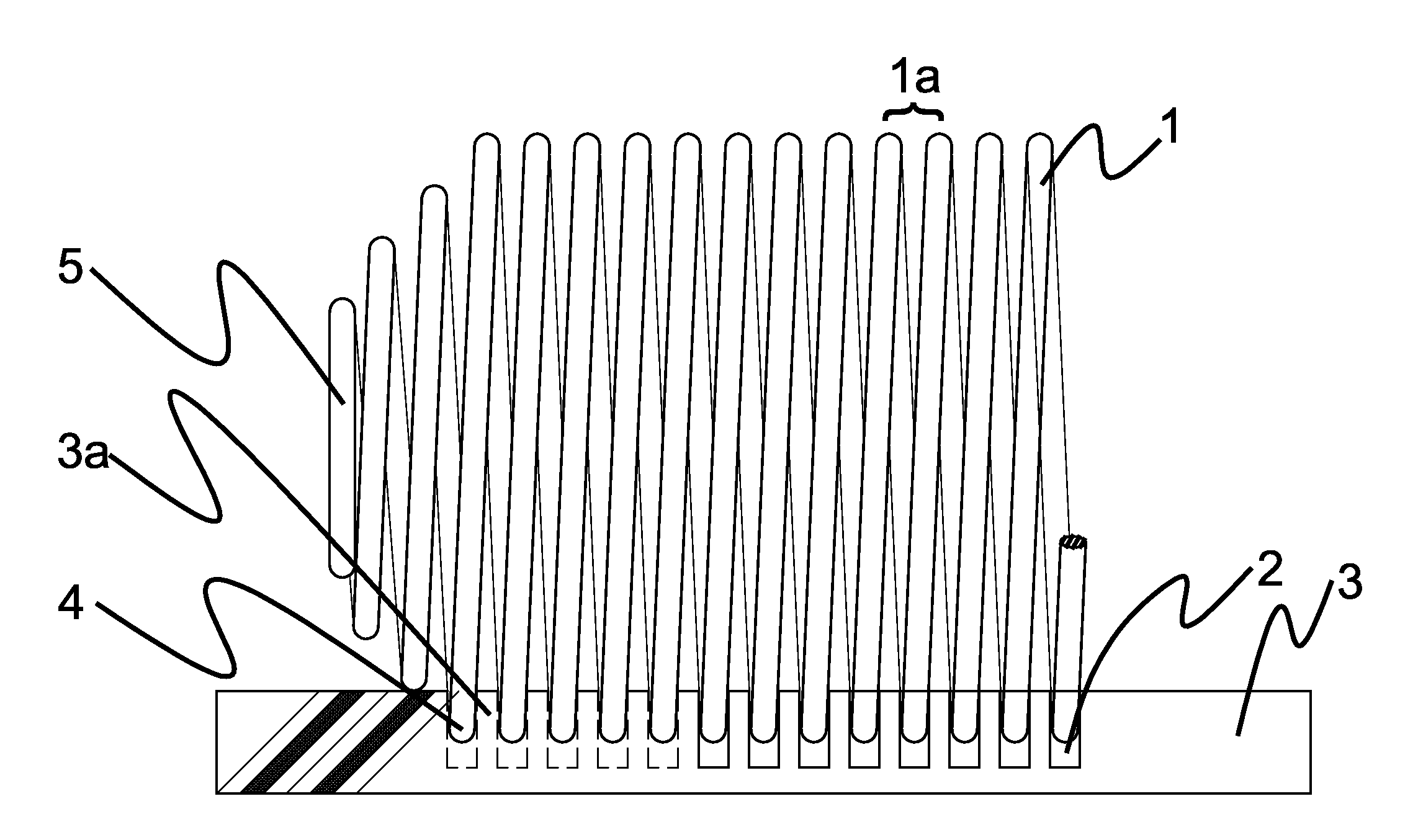
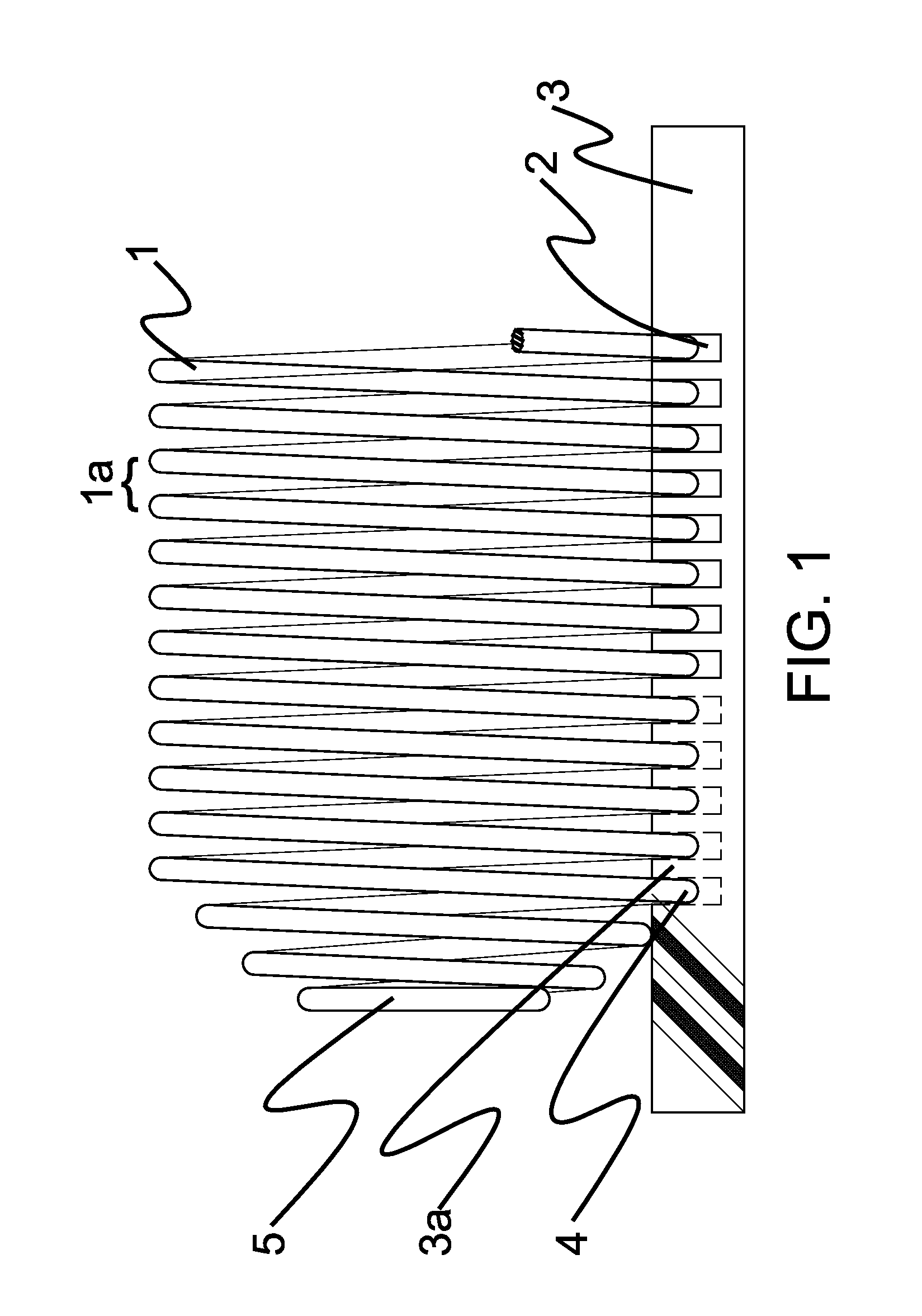
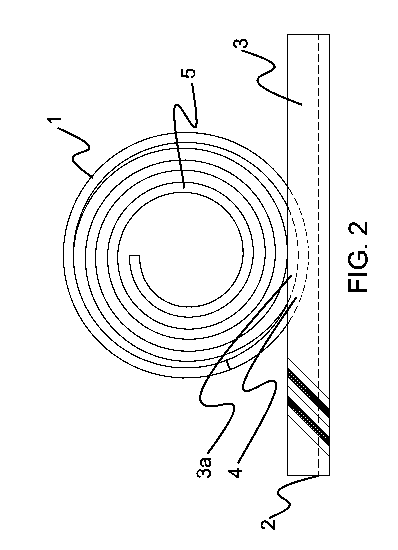
[0035]A 0.135″ OD type 302 stainless steel wire was wound to a 3.27″ OD (3″ ID) plurality of coils with a pitch of 2, terminating in 2 reduced-diameter coils with a final OD of 1″. A high density polyethylene (HDPE) cutting board base, 0.5″ thick and 6×6″ nominal, with 14 blind mortises 0.375″ deep and 2″ long centered therein, allowing the described plurality of coils to be embedded about 2.5 diameters, leaving lands about 2″ long inside the plurality of coils. The full inside diameter (ID, 3″) was available for inserting workpieces, and the land-to-inside top was about 2.7″ or 90% of the original ID. Blind mortises were vital; fourteen full mortises 0.375″ deep would have resulted in a 0.5″ board with unacceptable flexibility, unable to retain the plurality of coils.
[0036]Wire gauge is in the range of blade widths for kitchen knives, with a pitch that leaves a space about the width of such blades. In addition, one wants to cut thin slices if possible. For typical kitchen knives, w...
PUM
| Property | Measurement | Unit |
|---|---|---|
| OD | aaaaa | aaaaa |
| length | aaaaa | aaaaa |
| friction | aaaaa | aaaaa |
Abstract
Description
Claims
Application Information