Connector and connector assembly

a technology of connectors and assemblies, applied in the direction of couplings, coupling devices, manufacturing tools, etc., can solve the problems of poor operation feeling, deformation resiliently, and lock arms that interfere with locks, and achieve good operation feeling and connection resistance.

Active Publication Date: 2013-05-28
SUMITOMO WIRING SYST LTD
View PDF8 Cites 5 Cited by
  • Summary
  • Abstract
  • Description
  • Claims
  • Application Information

AI Technical Summary

Benefits of technology

[0024]If a connecting operation is performed with the operating portion pressed and the lock arm resiliently deformed, the lock arm contacts the second guiding surface without touching the first guiding surface. The second guiding surface has a relatively large angle of inclination with respect to the connecting direction of the two housings. Thus, connection resistance suddenly increases due to the contact of the lock arm with the second guiding surface and also in the process of the lock arm sliding in contact with the second guiding surface. An operator can clearly feel the progress of the connecting operation by this sudden variation of the connection resistance so that a good operation feeling is obtained even when the connecting operation starts with the lock arm resiliently deformed.

Problems solved by technology

The lock arm interferes with the lock in the process of connecting the two housings and deforms resiliently.
Japanese Unexamined Patent Publication No. 2008-130324 discloses a connector where a variation of connection resistance is small if the lock arm is deformed partially at the start of a connecting operation and thus provides a poor operation feeling.

Method used


Image

  • Connector and connector assembly
  • Connector and connector assembly
  • Connector and connector assembly

Examples


Embodiment Construction

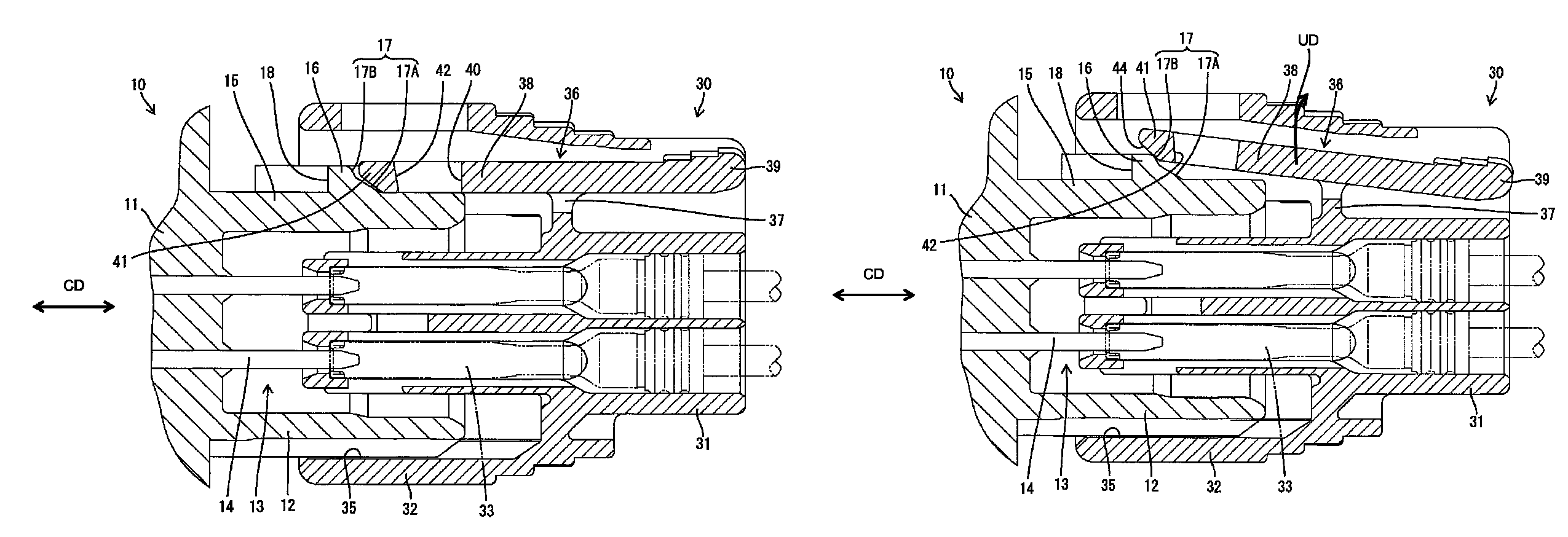
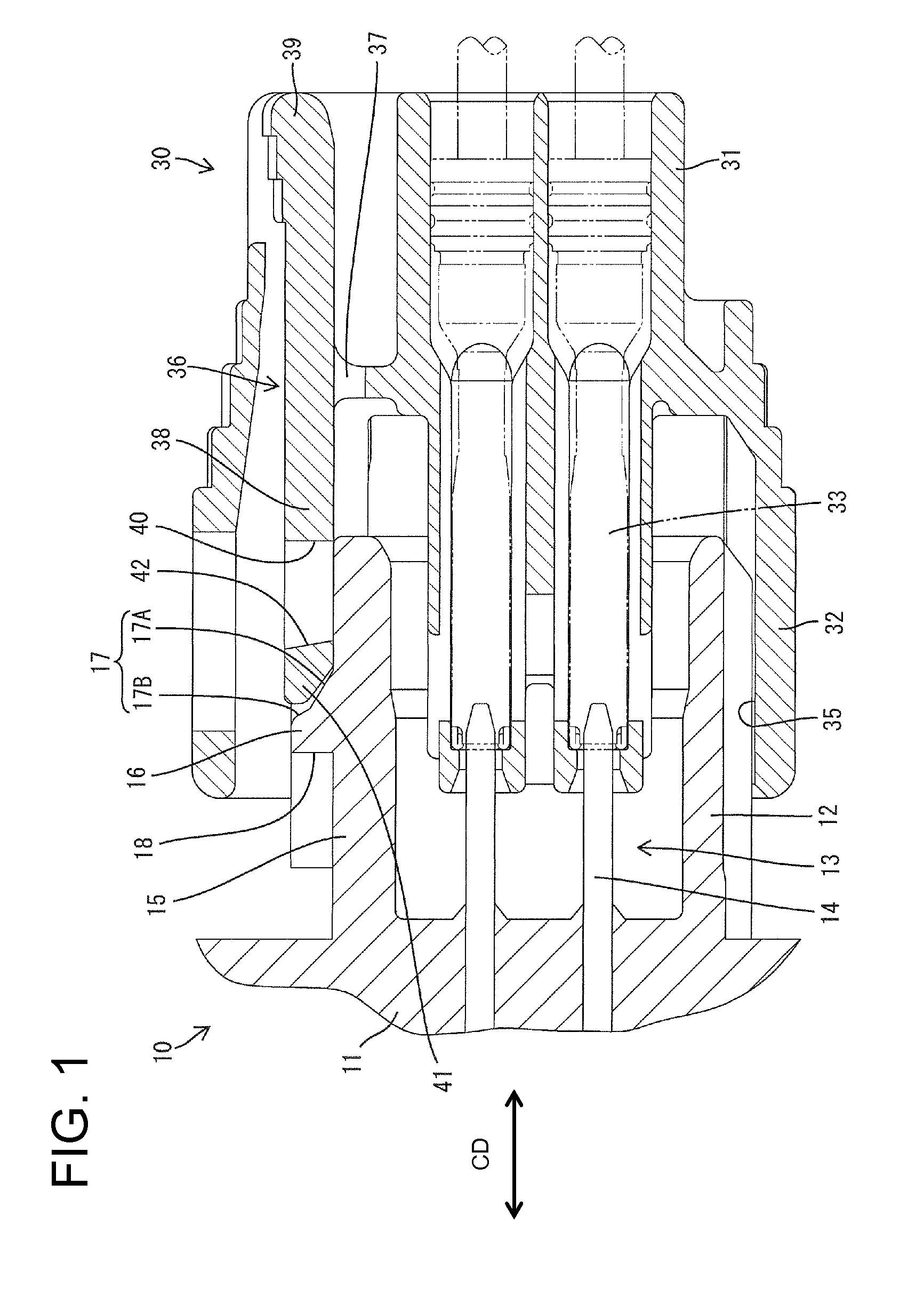
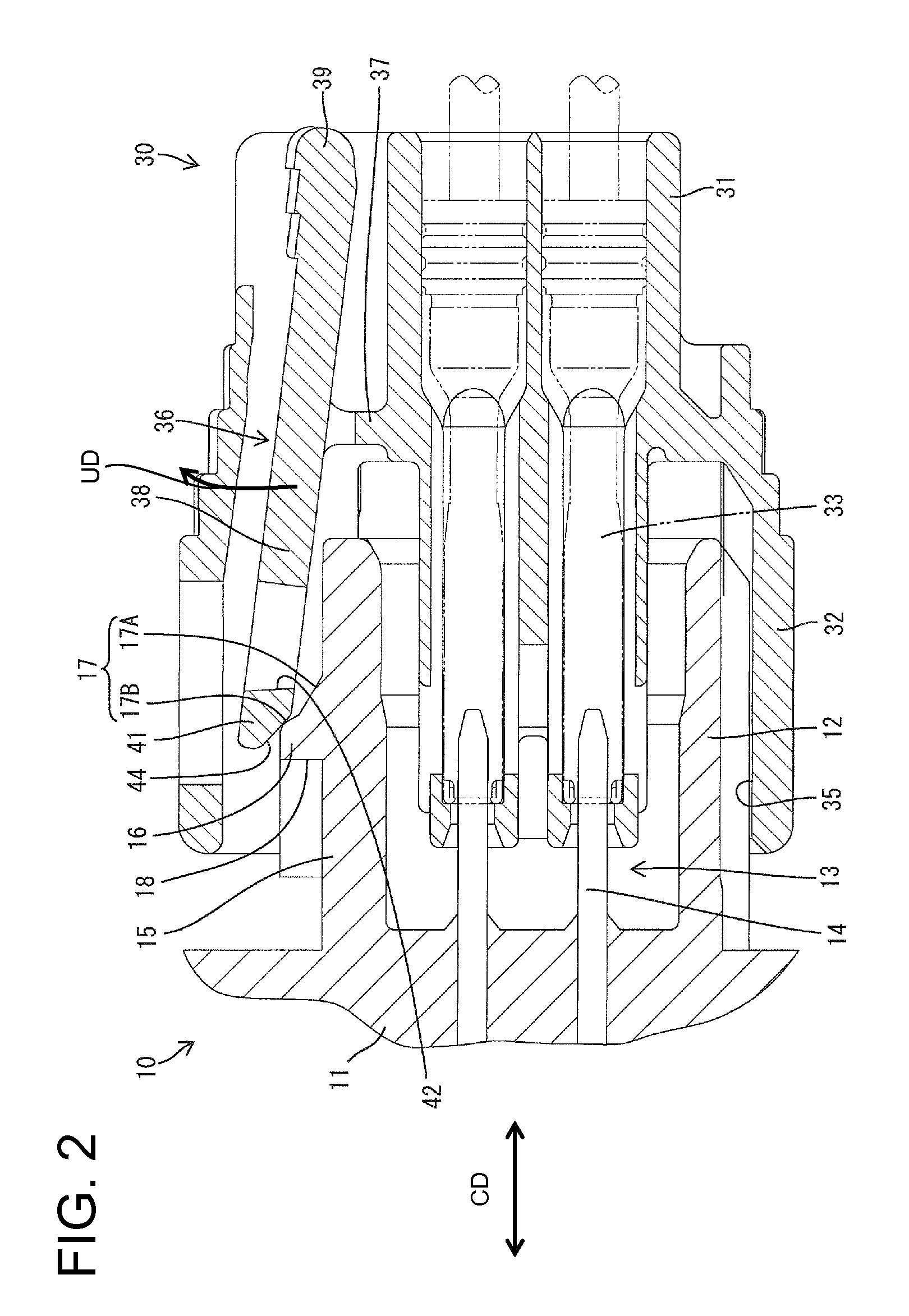
[0037]A connector in accordance with the invention is illustrated in FIGS. 1 to 9 and includes first and second housings 10 and 30 that are connectable to one another.

[0038]As shown in FIGS. 1 to 3, 6 and 7, the first housing 10 includes a terminal holding portion 11 and a substantially rectangular tubular receptacle 12 extending from the upper periphery of the front end (right end in FIGS. 1 to 3) of the terminal holding portion 11. Male terminal fittings 13 are held in the terminal holding portion 11, and tabs 14 at the leading ends of the terminal fittings 13 project forward from the terminal holding portion 11 to be at least partly surrounded by the receptacle 12.

[0039]The receptacle 12 is made of four plates, including an upper plate 15 with a flat upper surface that is parallel to a connecting direction CD of the two housings 10, 30. A lock 16 projects unitarily up from the upper surface of the upper plate 15. A guiding surface 17 is formed on the front (right surface in FIGS....


PUM


Abstract

In the process of connecting two housings (10, 30), a lock arm (36) is resiliently deformed in an unlocking direction crossing a connecting direction of the two housings (10, 30) by sliding in contact with a guiding surface (17) of a lock portion (16). The guiding surface (17) includes a first guiding surface (17A) arranged in a front area in the connecting direction to the second housing (30) and a second guiding surface (17B) arranged in an area behind the first guiding surface (17A) in the connecting direction to the second housing (30) and having a steep area (22) whose angle of inclination with respect to the connecting direction of the two housings (10, 30) is larger than that of the first guiding surface (17A).

Description

BACKGROUND OF THE INVENTION[0001]1. Field of the Invention[0002]The invention relates to a connector and to a connector assembly.[0003]2. Description of the Related Art[0004]Japanese Unexamined Patent Publication No. 2008-130324 discloses a connector with first and second housings that are connectable with one another. The first housing has a lock and the second housing has a resiliently deformable lock arm. The lock arm interferes with the lock in the process of connecting the two housings and deforms resiliently. The lock arm resiliently returns and engages the lock when the housings reach a properly connected state to lock the housings in the connected state.[0005]The lock has a guiding surface that is inclined with respect to a connecting direction of the two housings, and the lock arm is deformed by sliding in contact with the guiding surface in the process of connecting the housings. An operating portion formed on the lock arm can be pressed to deform the lock arm and to disen...

Claims


Application Information

Patent Timeline
Patent Type & Authority Patents(United States)
IPC IPC(8): H01R13/627
CPCH01R13/6272Y10T403/587F16B2200/71H01R13/639H01R13/42
Inventor SUZUKISAKURAI, TOSHIKAZU
Owner SUMITOMO WIRING SYST LTD
Why Eureka
Try Eureka