Connector

a technology of connecting rods and connecting rods, applied in the field of connecting rods, can solve the problems difficult deflection of the interference arm, poor resilience of the coupling, etc., and achieve the effects of low resistance between the housings, low resistance to bending, and easy deformation of the resilient structur

Active Publication Date: 2020-03-19
SUMITOMO WIRING SYST LTD
View PDF8 Cites 2 Cited by
  • Summary
  • Abstract
  • Description
  • Claims
  • Application Information

AI Technical Summary

Benefits of technology

[0008]The obliquely aligned couplings are sufficiently long to deform resiliently with ease so that the detecting body can tilt easily. As a result, connection resistance between the housings is low and the housings can be connected without any problem.
[0009]The tilting fulcrums of the couplings may be arranged at positions overlapping a tilting fulcrum of the lock arm in the front-rear direction. According to this configuration, tilting displacements of the detecting body and the lock arm can be synchronized smoothly.
[0010]The detector may include a fitting, and the housing may be fit into the fitting. The side walls may be configured on both side parts of the fitting. This configuration improves the strength of the side walls.

Problems solved by technology

Thus, the couplings have poor resilience and high rigidity.
As a result, the interference arm is difficult to deflect, and a large resistance may be generated to interfere with an operation of connecting the housings.

Method used


Image

  • Connector
  • Connector
  • Connector

Examples


Embodiment Construction

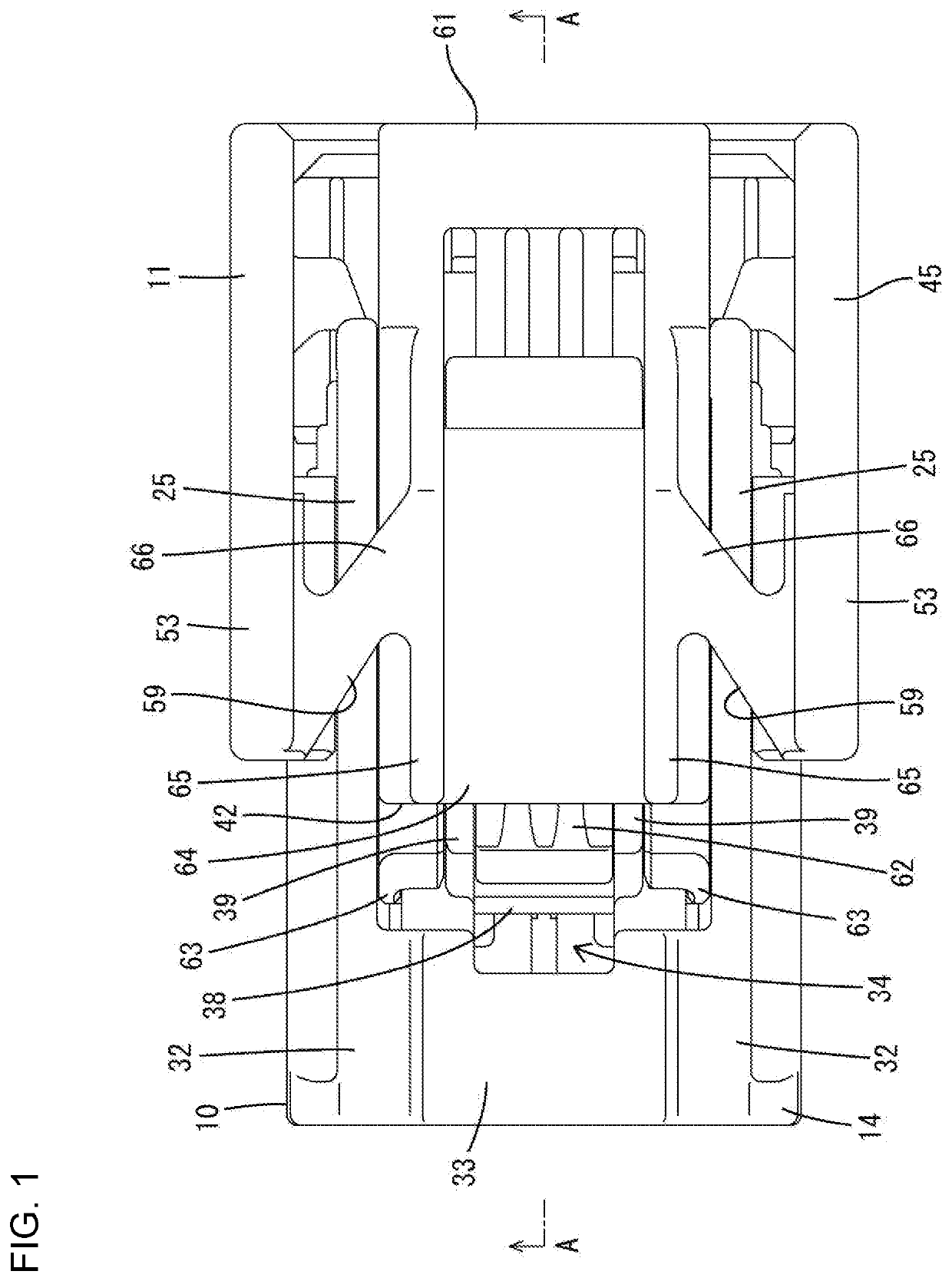
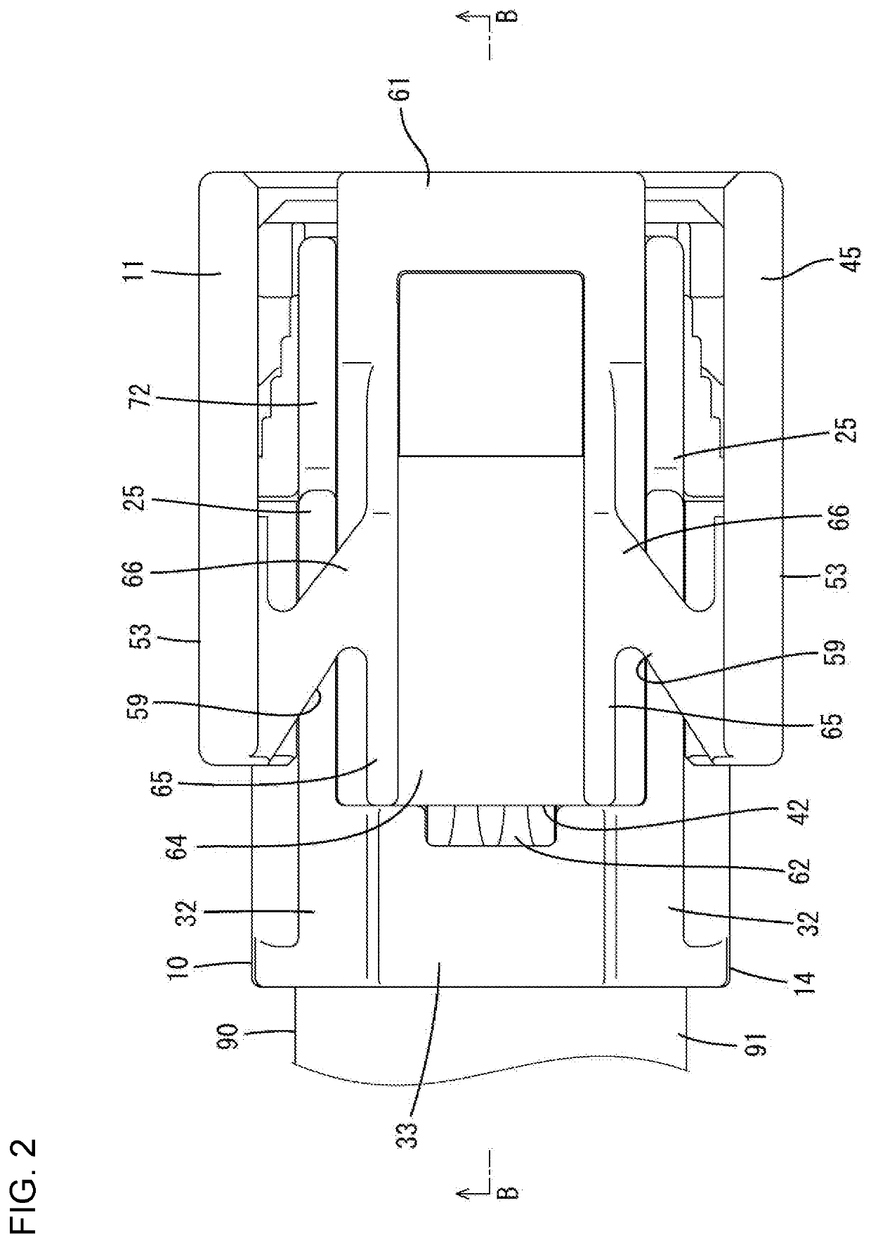
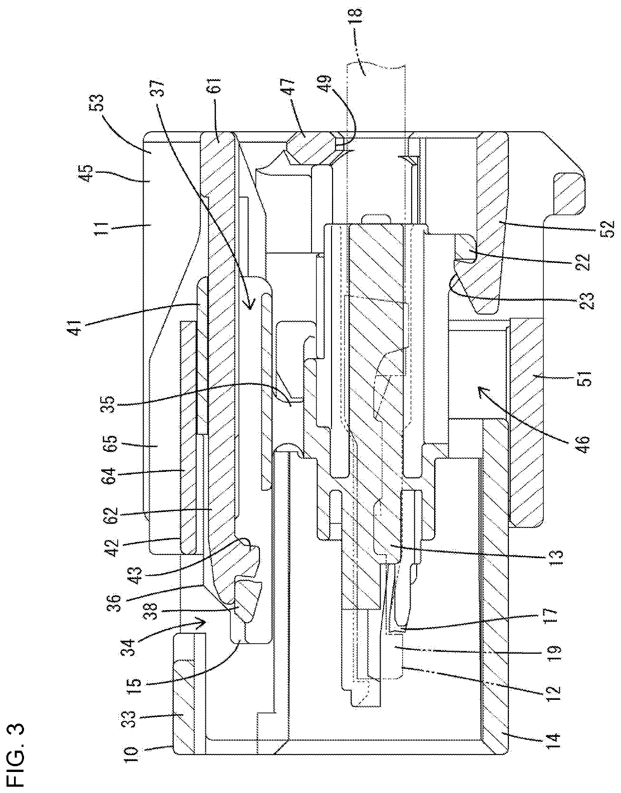
[0028]One embodiment is described with reference to FIGS. 1 to 17. A connector of this embodiment includes a housing 10, a detector 11 and terminal fittings 12. The housing 10 is connectable to a mating housing 90. Note that, in the following description, surfaces of the housing 10 and the mating housing 90 facing each other at the start of connection are referred to as front ends, and a vertical direction is based on FIGS. 3 to 5, 9 to 12, 14 and 15.

[0029]The mating housing 90 is made of synthetic resin and includes, as shown in FIGS. 4 and 5, a tubular receptacle 91 directly connected to an unillustrated device and projecting forward. Tab-like mating terminal fittings 92 project into the receptacle 91. The receptacle 91 includes a claw-like projecting lock 93 on the upper surface of an upper wall.

[0030]The housing 10 is made of synthetic resin and includes, as shown in FIGS. 14 to 16, a housing body 13, a fitting tube 14 and a lock arm 15.

[0031]As shown in FIG. 6, cavities 16 pene...


PUM


Abstract

A connector has a detector (11) is provided in a housing (10) for movement in a front-rear direction, and can move from a standby position to a detection position when the housing (10) is connected properly to a mating housing (90). The detector (11) includes two side walls (53) arranged to face each other in a width direction with a lock arm (15) provided on the housing (10) therebetween. A detecting body (42) is assembled with the lock arm (15) between the side walls (53) and can tilt together with the lock arm (15). Couplings (59) have tilting fulcrums (66) configured to resiliently deform when the detecting body (42) is tilted. The couplings (59) extend in oblique directions intersecting the width direction from the side walls (53) to corresponding side surfaces of the detecting body (42).

Description

BACKGROUNDField of the Invention[0001]The invention relates to a connector.Related Art[0002]Japanese Patent No. 4977404 discloses a connector that includes a connector housing and a tubular detector is mounted in the connector housing for movement between a restricting position and an allowing position.[0003]An opening is formed in an upper wall of the detector, and an interference arm extends in a front-rear direction in the opening. Couplings connect rear parts of both sides of the interference arm to opposed edges of the opening. A front of the interference arm has an interference projection that is locked to a lock arm of the connector housing.[0004]The interference projection and the lock arm ride on a lock projection of the mating connector as the connector housing and a mating connector are being connected, and the interference arm tilts with the couplings as supports. The detector moves from the allowing position to the restricting position when the connector housing is conn...

Claims


Application Information

Patent Timeline
Patent Type & Authority Applications(United States)
IPC IPC(8): H01R13/641H01R13/627H01R13/50
CPCH01R13/6272H01R13/50H01R13/641H01R13/46H01R13/639H01R13/64H01R13/426H01R13/428H01R13/627H01R13/629H01R13/743
Inventor LEE, MINHONAKAMURA, HIDETO
Owner SUMITOMO WIRING SYST LTD
Why Eureka
Try Eureka