
Common mode magnetic device for bus structure

a common-mode magnetic and bus-structure technology, applied in the direction of coupling device connection, magnetic core manufacturing, electrical apparatus casing/cabinet/drawer, etc., can solve the problems of difficult to fish the input or output cabling through the toroidal body of a traditional common-mode core, inconvenient positioning of a common-mode core at an available location, and inconvenient installation and/or maintenance of common-mode core features

Inactive Publication Date: 2013-06-04
ROCKWELL AUTOMATION TECH
View PDF12 Cites 17 Cited by
  • Summary
  • Abstract
  • Description
  • Claims
  • Application Information

AI Technical Summary

Benefits of technology

The patent describes a common mode core that can easily connect to a bus bar system. It consists of a mandrel with an opening through which magnetic tape is wound. This opening allows power to flow from the bus bars through the core without needing to bring the cabling together. This design simplifies the process of connecting the common mode core to the bus bar system.

Problems solved by technology

Traditional electrical cabinets, electrical components, common mode cores, and so forth make installation and / or maintenance of common mode core features inconvenient.
Further, it is now recognized that it can be difficult to fish the input or output cabling through the toroidal body of a traditional common mode core.
Also, positioning of a common mode core at an available location is often inconvenient.
For example, due to spatial limitations, a traditional common mode core may have to be positioned in a location that exposes the common mode core to additional wear and deterioration.

Method used


Image

  • Common mode magnetic device for bus structure
  • Common mode magnetic device for bus structure
  • Common mode magnetic device for bus structure

Examples


Embodiment Construction

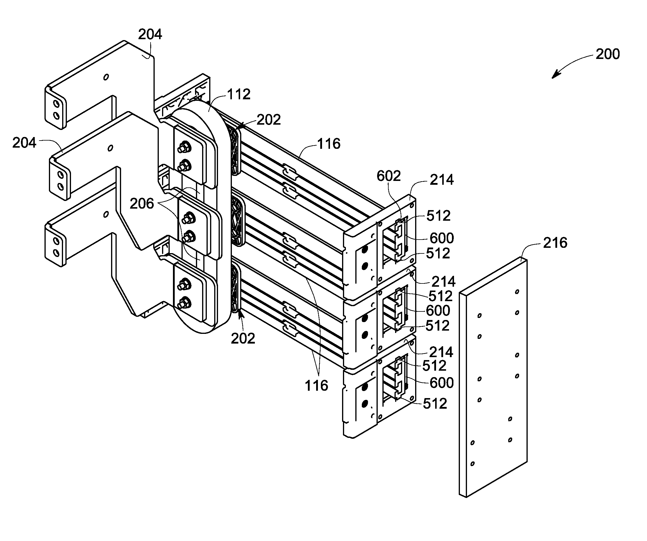
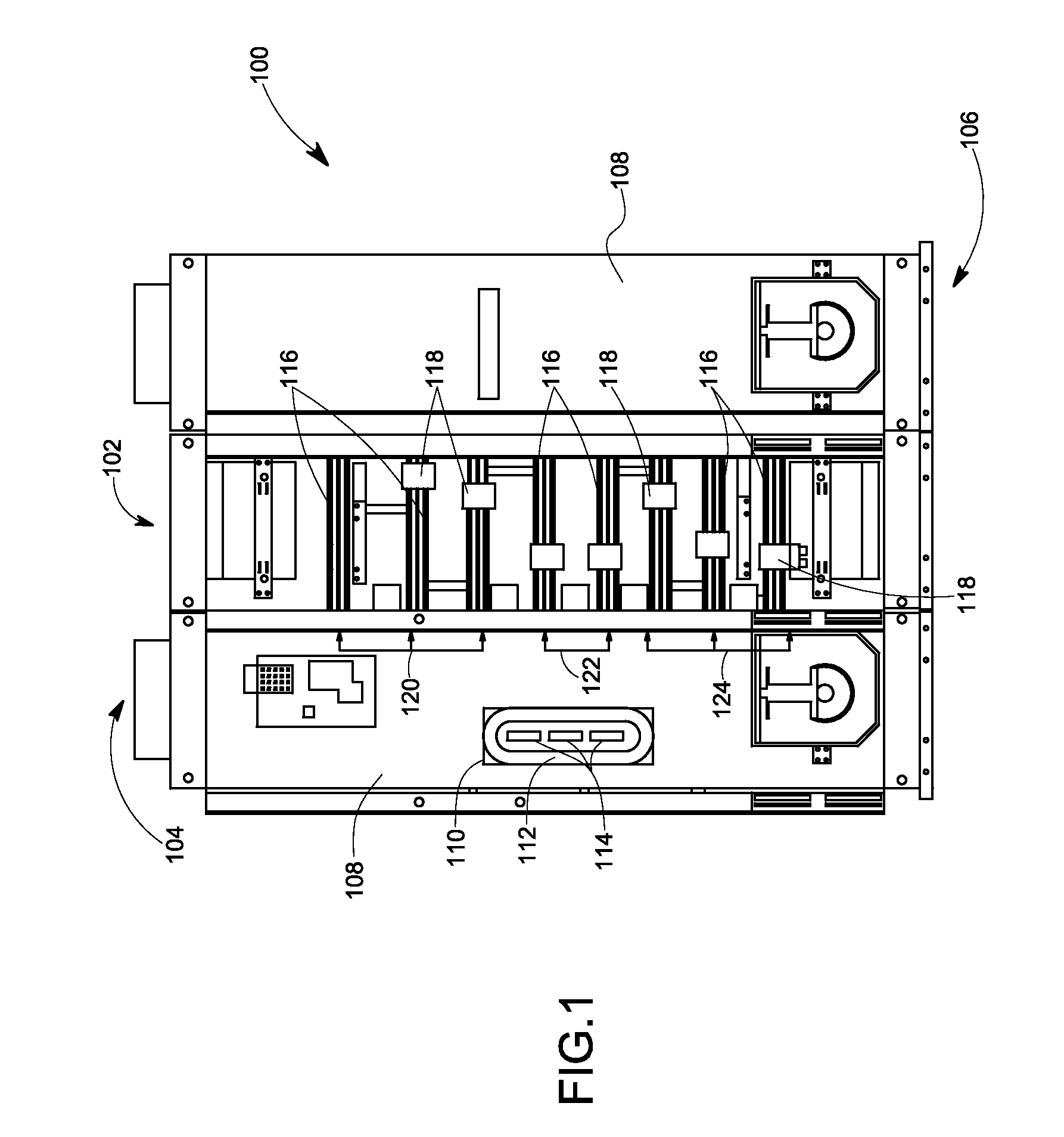
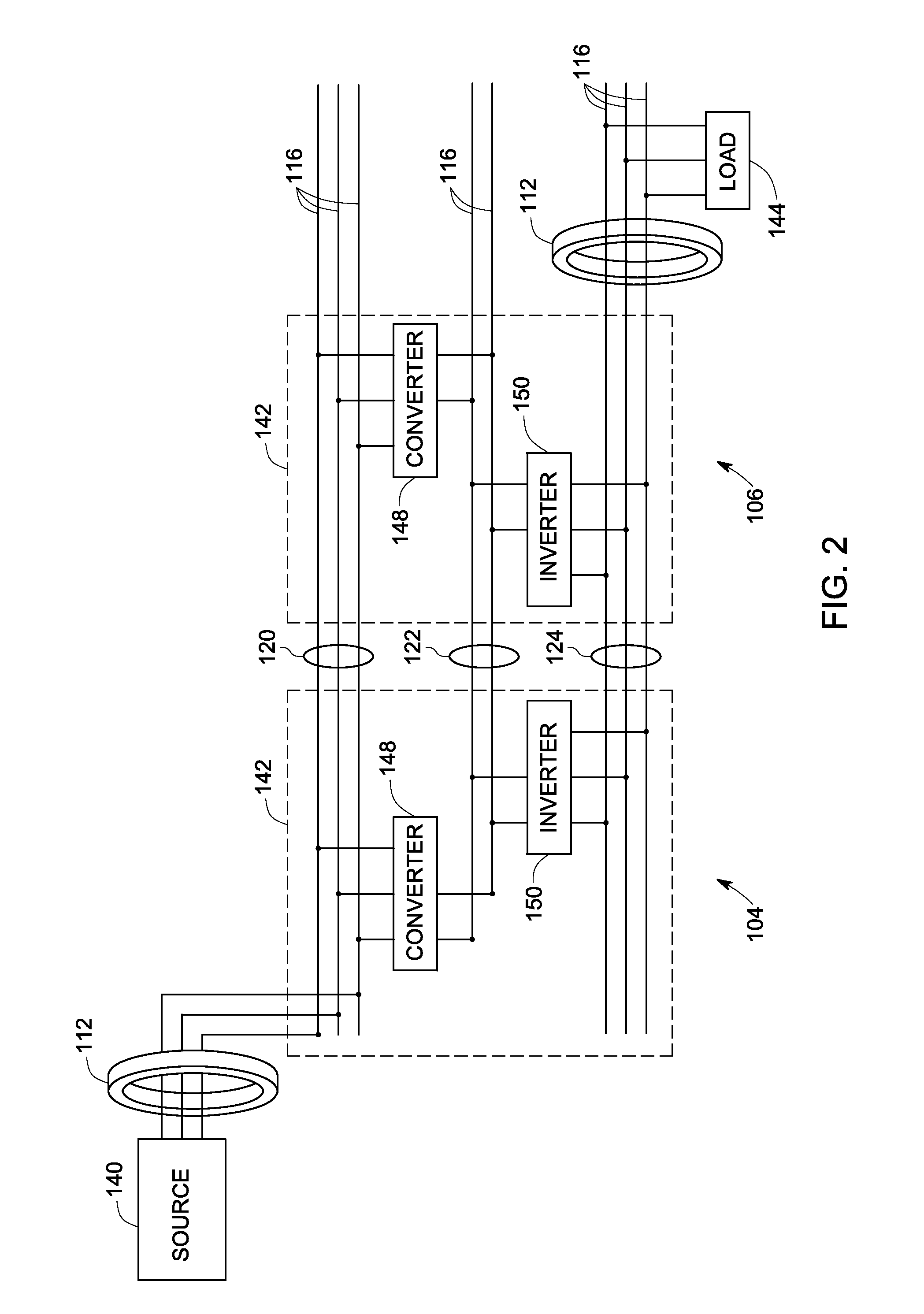
[0018]As discussed in detail below, embodiments of the present technique function to provide a common mode magnetic device (e.g., a common mode core) configured to conveniently function with a bus structure of a drive system or the like. In particular, the present technique relates to providing a common mode magnetic device that is configured to cooperate with bus bars or related extensions within the enclosure. For example, one embodiment includes a common mode core that is configured to surround conductive extensions from a receptacle formed in an outer wall of an electrical enclosure. The common mode magnetic device is generally obround and configured to be positioned about a plurality of conductive extensions and non-conductive supports that are coupled to respective bus bars. The conductive extensions may include elongate via blocks and / or bus extensions that each couple to the face of a bus bar such that current from the bus bar can be conducted in a direction traverse to the ...


PUM


Abstract

A magnetic device mounting system is disclosed, such as for use in electrical cabinets for distribution of power via power bus bars. The system includes a common mode magnetic device that has an opening configured to receive extensions of a set of parallel bus bars. A non-conductive support is provided, along with a conductive extension, the non-conductive support and extension being configured to coordinate to engage the opening and to support the common mode magnetic device via attachment to the bus bar.

Description

BACKGROUND[0001]The present invention relates generally to the field of power electronic devices such as those used in power conversion or applying power to motors and similar loads. More particularly, the invention relates to a common mode magnetic device configured to cooperate with a bus structure.[0002]In the field of power electronic devices, a wide range of circuitry is known and currently available for transmitting, converting, producing, and applying power. Depending upon the application, such circuitry may transmit incoming power to various devices and / or convert incoming power from one form to another as needed by a load. In a typical drive system arrangement, for example, constant or varying frequency alternating current power (e.g., from a utility grid or generator) is converted to controlled frequency alternating current power that can be used to drive motors and other loads. In this type of application, the frequency of the output power can be regulated to control the ...

Claims


Application Information

Patent Timeline
Patent Type & Authority Patents(United States)
IPC IPC(8): H02B1/20
CPCH01F41/0213H01F27/266H01F3/04H01F27/04H01F17/06H01F2017/0093H01F2017/065
Inventor TALLAM, RANGARAJAN M.KEEGAN, JEREMY J.RILEY, PATRICK J.DAY, SCOTT D.
Owner ROCKWELL AUTOMATION TECH
Learn More