Sound reproduction with improved low frequency characteristics

a low frequency, sound reproduction technology, applied in the direction of transducer details, instruments, electrical transducers, etc., can solve the problems of difficult design of relatively low frequency horns, difficult to make horn drivers, and listeners being unable to position “on axis”

Active Publication Date: 2013-06-04
DANLEY THOMAS J
View PDF11 Cites 14 Cited by
  • Summary
  • Abstract
  • Description
  • Claims
  • Application Information

AI Technical Summary

Problems solved by technology

The design of relatively low frequency horns encountered challenging problems because of the mass and acoustic size required.
However, difficulties arose in attempts to make a horn driver having a relatively flat acoustic power response above 2 or 3 kHz.
However, situations arose where listeners could not be positioned “on axis”.
Most notably, severe high frequency roll off was experienced as a listener moved away from the central axis of the sound reproduction system.
Unfortunately, practical constant directivity horns produced considerably less low-frequency loading on the drivers than the popular exponential-shape curved wall horns for which improvements were sought.

Method used


Image

  • Sound reproduction with improved low frequency characteristics
  • Sound reproduction with improved low frequency characteristics
  • Sound reproduction with improved low frequency characteristics

Examples


Embodiment Construction

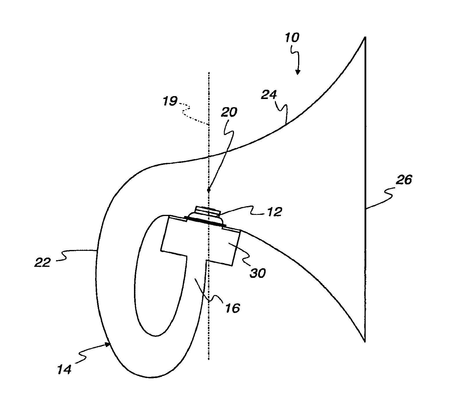
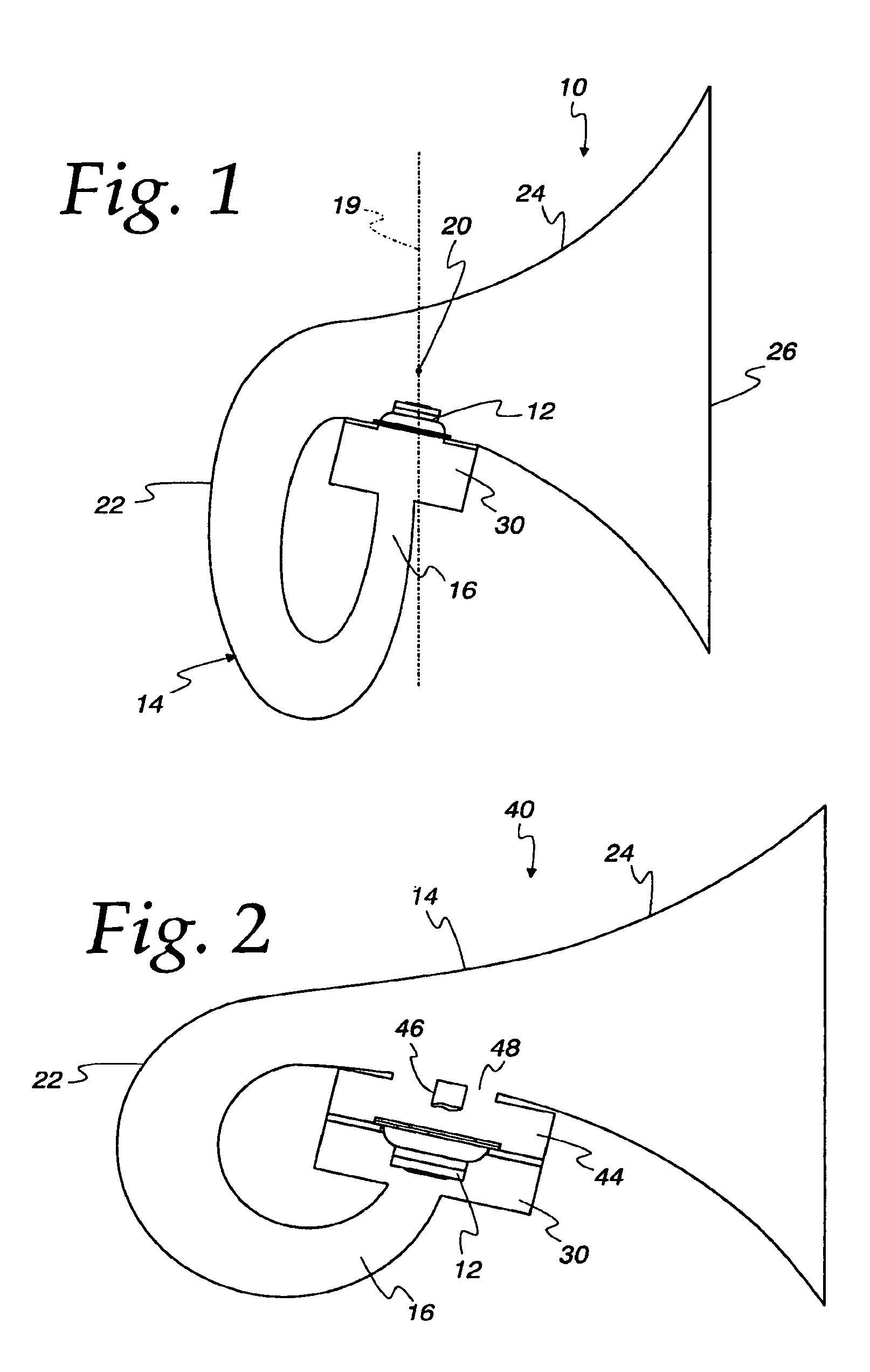
[0020]The invention disclosed herein is, of course, susceptible of embodiment in many different forms. Shown in the drawings and described herein below in detail are the preferred embodiments of the invention. It is to be understood, however, that the present disclosure is an exemplification of the principles of the invention and does not limit the invention to the illustrated embodiments.

[0021]For ease of description, sound reproduction systems embodying the present invention are described herein below in their usual assembled position as shown in the accompanying drawings and terms such as front, rear, upper, lower, horizontal, longitudinal, etc., may be used herein with reference to this usual position. However, the sound reproduction systems may be manufactured, transported, sold, or used in orientations other than that described and shown herein.

[0022]At the outset it is noted that, while many different types of sound reproduction systems can receive substantial benefit from th...


PUM


Abstract

A sound reproduction system (10) is disclosed in which a sound barrier (14) defines a horn passageway having an upstream (22) and a downstream section (24). A driver (12) is mounted at the throat (16) of the upstream section (22) so that its rearward directed output communicates with the downstream section (24). Output from the upstream section and the rearward directed output of the driver are merged at a tap point located at the beginning of the downstream section. By altering the respective areas and lengths of the upstream and downstream sections a variety of different frequency dependent responses are obtained. In one example, low-frequency response systems of heretofore unobtainable compact size are realized.

Description

CROSS-REFERENCE TO RELATED APPLICATIONS[0001]This application is a U.S. National Stage of PCT / US2007 / 006483, filed Mar. 14, 2007, and claims benefit of U.S. Provisional Patent Application No. 60 / 782,401, filed Mar. 15, 2006, each of which is incorporated herein by reference in its entirety.FIELD OF THE INVENTION[0002]The present invention relates to sound reproduction systems having one or more drivers coupled to a sound barrier.DESCRIPTION OF THE RELATED ART[0003]Originally, the art of horn loading of drivers was done to increase the electroacoustic efficiency of the drivers. Various techniques were employed early on to make the most of limited amplifier power and relatively low power handling capabilities of available drivers. Early efforts were centered around obtaining the greatest sound level possible. Horn loaded speakers, sometimes referred to simply as “horns”, of this early era were generally designed to have a specific expansion rate throughout, and typically were made to ...

Claims


Application Information

Patent Timeline
Patent Type & Authority Patents(United States)
IPC IPC(8): H04R1/20
CPCH04R1/30H04R1/2865
Inventor DANLEY, THOMAS J.
Owner DANLEY THOMAS J
Why Eureka
Try Eureka