Ventilation pressure leakage sound barrier module

A sound barrier and pressure relief technology, which is applied in construction, noise absorption devices, etc., can solve the problems of regenerative noise, pressure loss increase of the pressure relief module, area length limitation, etc., to achieve lower structural requirements, lower length limitation, Requirement reduction effect

Active Publication Date: 2010-10-13
ZISEN ENVIRONMENTAL TECHNOLOGY CO LTD
View PDF10 Cites 15 Cited by
  • Summary
  • Abstract
  • Description
  • Claims
  • Application Information

AI Technical Summary

Problems solved by technology

[0003] The current sound barrier is usually a whole board without a through hole. There is a sound-absorbing and muffling material in the board or a sound-absorbing and muffling layer on the base plate, which plays a good role in sound insulation and noise reduction. The application number is 200720076470.1 Chinese patent "A Sound Barrier for High-speed Railway Noise Protection". However, the sound barriers currently used for railways are usually closer to the track in order to achieve a better noise reduction effect (generally from the center line of the railroad track) 4m or so), when the train passes at high speed, the sound barrier will be affected by the natural wind load and the train wind load at the same time. The train wind load is caused by the pressure wave generated by the passing train. Under the joint action of the sound barrier components on both sides of the line, a strong pulsating force will be generated on the surface of the sound barrier components on both sides of the line. Due to the defects of the sound barrier structure without through holes, the ventilation and pressure relief cannot be timely, so the sound barrier itself needs to be able to withstand the resulting noise for a long time. The mechanical load of the sound barrier component, especially the shell of the metal sound barrier component must have a large thickness
Due to reliability and economic considerations, multi-dimensional metal forming processes are only feasible for materials with a certain thickness, thereby limiting the load-carrying capacity
Therefore, in order to ensure the necessary mechanical bearing capacity, the area, especially the reachable length, of each sound insulation component of the railway sound barrier is limited. Components, the installation of railway sound barriers and the manufacturing costs of their components are relatively high, and at the same time, the common road sound barrier components, especially metal sound barriers, are restricted in the application of railway traffic noise control
[0004] In addition, there are currently sound barriers that can ventilate and relieve pressure. The louver-like structure with fixed blades can be used to ventilate and relieve pressure through the passages between the louver blades. This structure is currently generally used in industrial noise control, and it is called anechoic louvers in the industry. , but has not been used in the field of high-speed rail noise reduction
However, since the blades are fixed, the size of the ventilation channel is also fixed, so the ability of its ventilation and pressure relief is also fixed.
However, the speed of the train and the direction of travel may be different. The natural environment of the railroad track, including factors such as temperature, humidity, wind force and wind direction, is constantly changing. Therefore, the air flow speed, direction and air volume will also change constantly. If ventilation If the size of the channel remains unchanged, the optimal state may not be achieved due to untimely or uneven ventilation and pressure relief, which will make the flow field more complex and uneven, increase the pressure loss of the pressure relief module, and may also generate regenerative noise , resulting in poor ventilation, pressure relief, sound absorption, and sound insulation effects of the overall sound barrier

Method used


Image

  • Ventilation pressure leakage sound barrier module
  • Ventilation pressure leakage sound barrier module
  • Ventilation pressure leakage sound barrier module

Examples


Embodiment 1

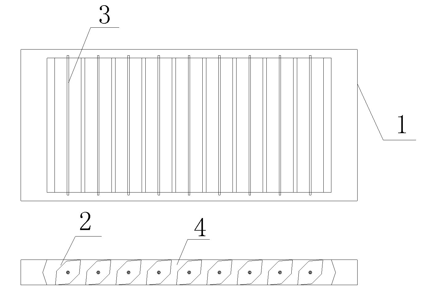
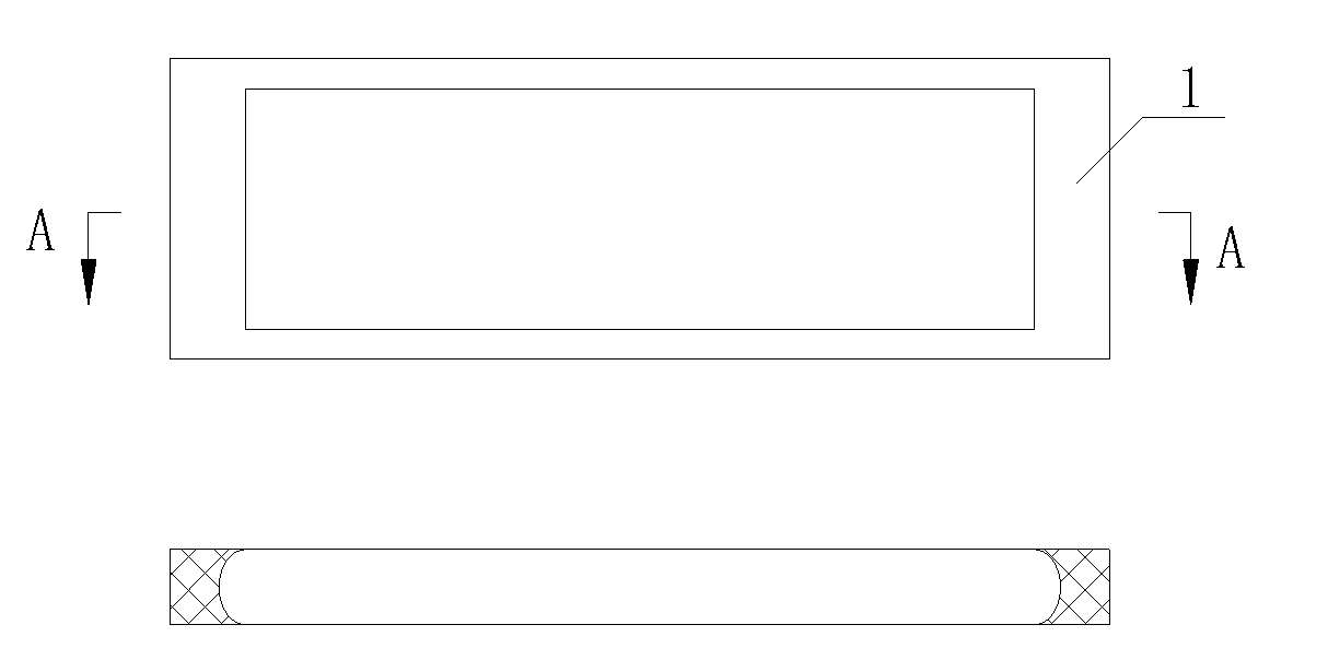
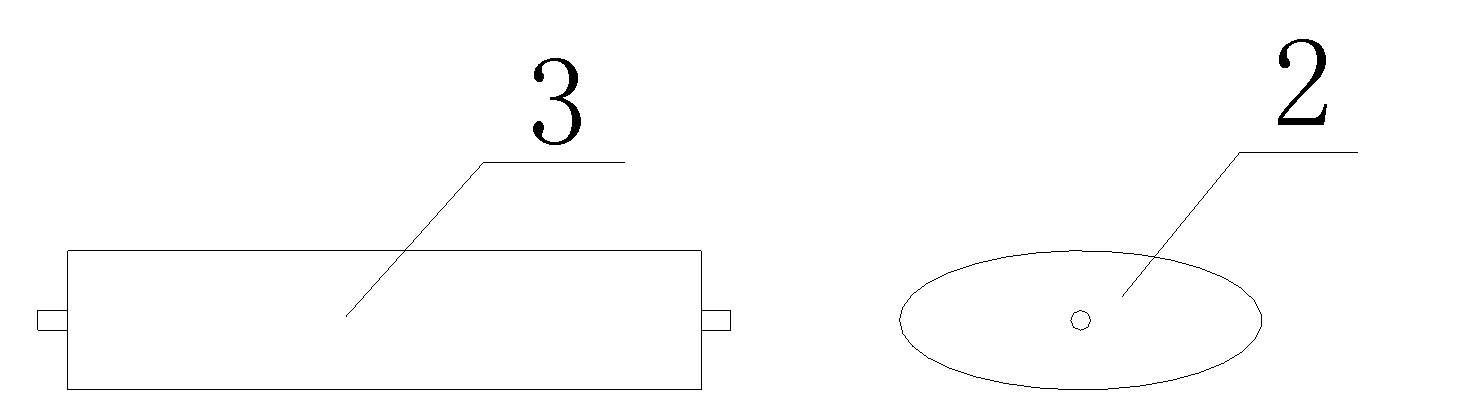
[0029] Such as Figures 1 to 3 As shown, the ventilation and pressure relief sound barrier module of this embodiment is composed of a rigid frame 1, several silencing blades 2 and adjusting screws 3, the silencing blades 2 are in one-to-one correspondence with the adjusting screws 3, and the adjusting screws 3 pass through the silencing Acoustic vane 2, so that muffler vane 2 can freely rotate around adjusting screw rod 3, thereby forming air channel 4 whose channel size can be automatically adjusted. Rigid frame 1 is a rectangular ring structure made of aluminum, filled with sound-absorbing material wrapped in non-woven fabrics between the rectangular rings, the inner circumference of the rigid frame 1 and the side facing the track during use are perforated plate structures, the perforation rate ≥ 23%; the peripheral surface of the outer ring of the rigid frame 1 and the side facing away from the track during use are blind plate structures. In order to be able to replace exi...


PUM


Abstract

The invention discloses a ventilation pressure leakage sound barrier module, belonging to the noise reduction field. The module comprises a ring-shaped rigidity frame, a plurality of regulation screws and noise elimination vanes which correspond to the regulation screws and can freely rotate around the regulation screws; the noise elimination vanes are arranged in the ring-shaped frame regularly to form a shutter structure which can freely rotate. The module of the invention adopts the rotatable design of the noise elimination vanes, can reach more excellent ventilation noise elimination effect by regulating the wind facing angle of the module, realize free selection of different noise elimination ranges and ventilation amount, and simultaneously also changes the direction of noise radiation; in addition, the rotatable design of the noise elimination vanes can lead the module to automatically regulate the ventilation angle of the noise elimination vanes according to different travelling directions of vehicles, thus achieving the best noise elimination and pressure leakage effects.

Description

technical field [0001] The invention relates to a sound barrier module, in particular to a ventilation and pressure relief sound barrier module for railways. Background technique [0002] In the high-speed railway (train speed ≥ 200km / h), when the train passes at high speed, it will be affected by the natural wind load and the train wind load together, which will generate a lot of noise pollution. In order to reduce this pollution, noise is usually installed on both sides of the rail Barriers for sound insulation and sound attenuation. [0003] The current sound barrier is usually a whole board without a through hole. There is a sound-absorbing and muffling material in the board or a sound-absorbing and muffling layer on the base plate, which plays a good role in sound insulation and noise reduction. The application number is 200720076470.1 Chinese patent "A Sound Barrier for High-speed Railway Noise Protection". However, the sound barriers currently used for railways are u...

Claims


Application Information

Patent Timeline
Patent Type & Authority Applications(China)
IPC IPC(8): E01F8/00
Inventor 贾荷香沈加曙
Owner ZISEN ENVIRONMENTAL TECHNOLOGY CO LTD
Why Eureka
Try Eureka