Sound source direction judging device and method as well as microphone directivity regulating system and method

A technology of direction judgment and microphone, which is applied in the direction of sound-emitting devices, microphone mouth/microphone accessories, speech analysis, etc., and can solve problems such as inability to accurately determine the direction of the sound source, and inability to receive signals well

Active Publication Date: 2016-12-21
QINGDAO GOERTEK
View PDF6 Cites 35 Cited by
  • Summary
  • Abstract
  • Description
  • Claims
  • Application Information

AI Technical Summary

Problems solved by technology

[0003] In view of the above problems, the present invention provides a sound source direction judging device and method, and a microphone directivity adjustment system and method to solve the problem in the prior art that the direction of the microphone array can only be fixed to the default sound direction due to the inability to accurately judge the sound source direction. The source location, the problem of not receiving the signal well

Method used


Image

  • Sound source direction judging device and method as well as microphone directivity regulating system and method
  • Sound source direction judging device and method as well as microphone directivity regulating system and method
  • Sound source direction judging device and method as well as microphone directivity regulating system and method

Examples


Embodiment 1

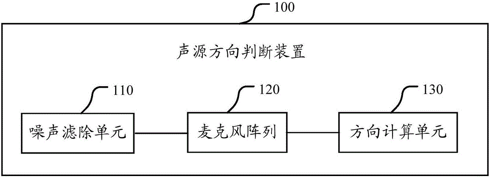
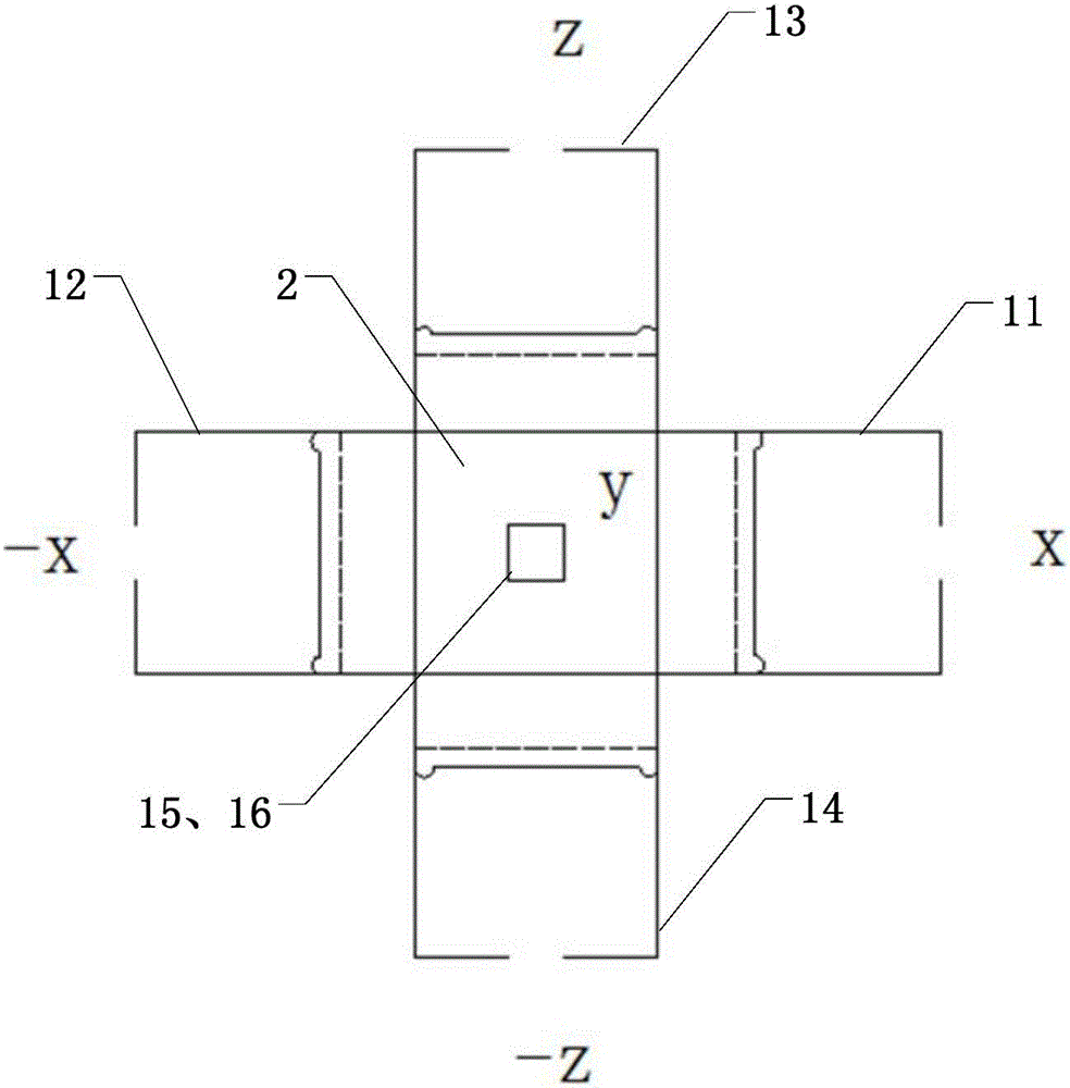
[0043] Such as figure 1 and figure 2 As shown, the embodiment of the present invention provides a sound source direction judging device 100, including: a noise filtering unit 110, a direction calculation unit 130, and a figure 2 The shown microphone array 120 consists of three pairs of microphones symmetrically distributed in the positive and negative directions of the X axis, the positive and negative directions of the Y axis, and the positive and negative directions of the Z axis. The three pairs of microphones 11-16 are fixed to each other through the XYZ axis joint 2. Specifically, the direction calculation unit 130 may be, for example, a DSP chip.

[0044] The microphone array 120 receives the sound wave signal of the sound source, and transmits the received sound wave signal to the noise filtering unit 110;

[0045] The noise filtering unit 110 filters out noise signals in frequency bands other than the frequency band (300Hz~3.4kHz) where the sound source is located...

Embodiment 2

[0061] In the second embodiment of the present invention, in order to reduce the amount of calculation of the direction calculation unit, it can be pre-determined according to the use of the microphone array whether the sound wave received by the microphone array is from a close-range sound source or a long-distance sound source. In the microphone array, the algorithm programs corresponding to the short-distance sound source and the long-distance sound source are pre-stored in the direction calculation unit respectively. If in most usage occasions, the sound waves received by the microphone array are all from close-range sound waves, the algorithm program in the direction calculation unit is pre-stored to calculate the direction coordinates of the sound source according to the sound pressure value, that is, the coordinates are (P x+ -P x- , P y+ -P y- , P z+ -P z- ). If in most usage occasions, the sound waves received by the microphone array are all from long-distance so...

Embodiment 3

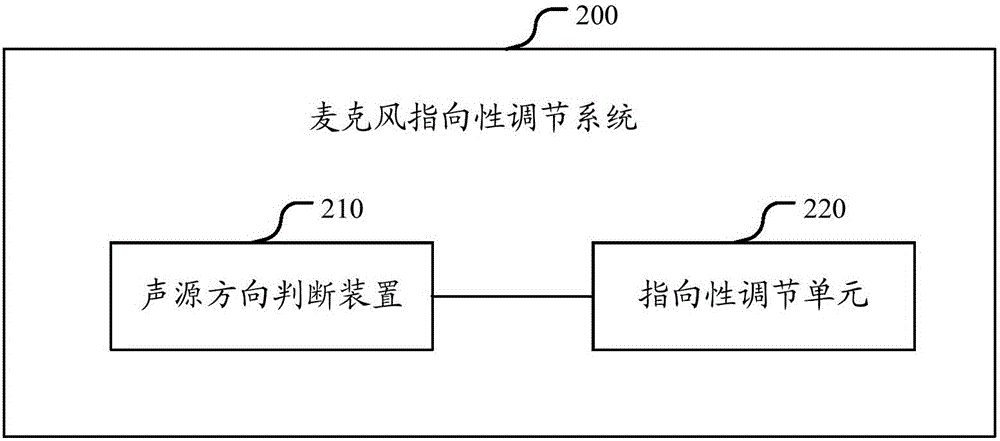
[0070] Such as image 3 As shown, the embodiment of the present invention also provides a microphone directivity adjustment system 200 , including a sound source direction judging device 210 and a directivity adjustment unit 220 .

[0071] In this embodiment of the present invention, the sound source direction judging device 210 is the same as the sound source direction judging device 100 in Embodiment 1, and will not be repeated here.

[0072] The directivity adjustment unit 220 acquires the direction coordinates of the sound source calculated by the sound source direction judging device 210, and adjusts the beam direction of the microphone so that it points to the direction coordinates of the sound source. When adjusting the beam direction of the microphones, only a part of the microphones or all the microphones may be adjusted according to needs, so as to control the beam of the microphone array 120 to precisely point to the sound source.

[0073] In the embodiment of the ...


PUM


Abstract

The invention discloses a sound source direction judging device, a sound source direction judging method as well as a microphone directivity regulating system and a microphone directivity regulating method. The sound source direction judging device comprises a noise filtering unit, a direction computing unit, and a microphone array composed of three pairs of microphones symmetrically distributed in the positive and negative directions of the X axis, the Y axis and the Z axis, wherein the microphone array is used for receiving sound wave signals of a sound source, and transmitting the sound wave signals to the noise filtering unit; the direction computing unit is used for calculating direction coordinates of the sound source according to the sound wave signals with noise signals filtered out, and judging the direction of the sound source according to the direction coordinates of the sound source. A directivity regulating unit of the microphone directivity regulating system obtains the direction coordinates of the sound source calculated by the sound source direction judging device, regulates the beam direction of the microphone array so that the beam direction is towards the direction coordinates of the sound source, and controls the microphone array to only receive sound waves emitted from the sound source direction, so that voice signals are well received, good voice enhancement and noise attenuation effects are realized, and the effectiveness and reliability of speech communication are realized.

Description

technical field [0001] The invention relates to the field of microphone speech enhancement and noise reduction, in particular to a sound source direction judging device and method, and a microphone directivity adjustment system and method. Background technique [0002] A microphone array is composed of more than two microphones arranged in a specific spatial shape. The research on microphone array speech enhancement methods began in the 1980s. After that, scholars from various countries gradually proposed speech enhancement algorithms based on microphone arrays according to different noise conditions. In the microphone speech enhancement and noise reduction system in the prior art, since the direction of the sound source cannot be accurately judged, the directivity of the microphone array is fixed, that is, during the application process of the product, the direction of the microphone array is fixed to the default sound source position. However, when the relative position o...

Claims


Application Information

Patent Timeline
Patent Type & Authority Applications(China)
IPC IPC(8): G10K11/34G10L21/0208H04R1/08
Inventor 张晓红
Owner QINGDAO GOERTEK
Why Eureka
Try Eureka