Lighting fixture

a technology of lighting fixtures and fixtures, which is applied in the direction of fixed installation, lighting and heating equipment, lighting support devices, etc., can solve the problems of heavy weight of fluorescent fixtures, the casing and associated hardware needed for operation, and the difficulty of manufacturing, storage and shipping

Active Publication Date: 2013-06-11
ESMAILZADEH ASHKAN +1
View PDF4 Cites 62 Cited by
  • Summary
  • Abstract
  • Description
  • Claims
  • Application Information

AI Technical Summary

Benefits of technology

[0012]One or more cooling fins are coupled to the outside surface of the top portion of the hat shaped bracket, or in some embodiments, from the side portions, and extend away

Problems solved by technology

As a result, such fluorescent fixtures including the reflectors, casing and associated ha

Method used


Image

  • Lighting fixture
  • Lighting fixture
  • Lighting fixture

Examples


Embodiment Construction

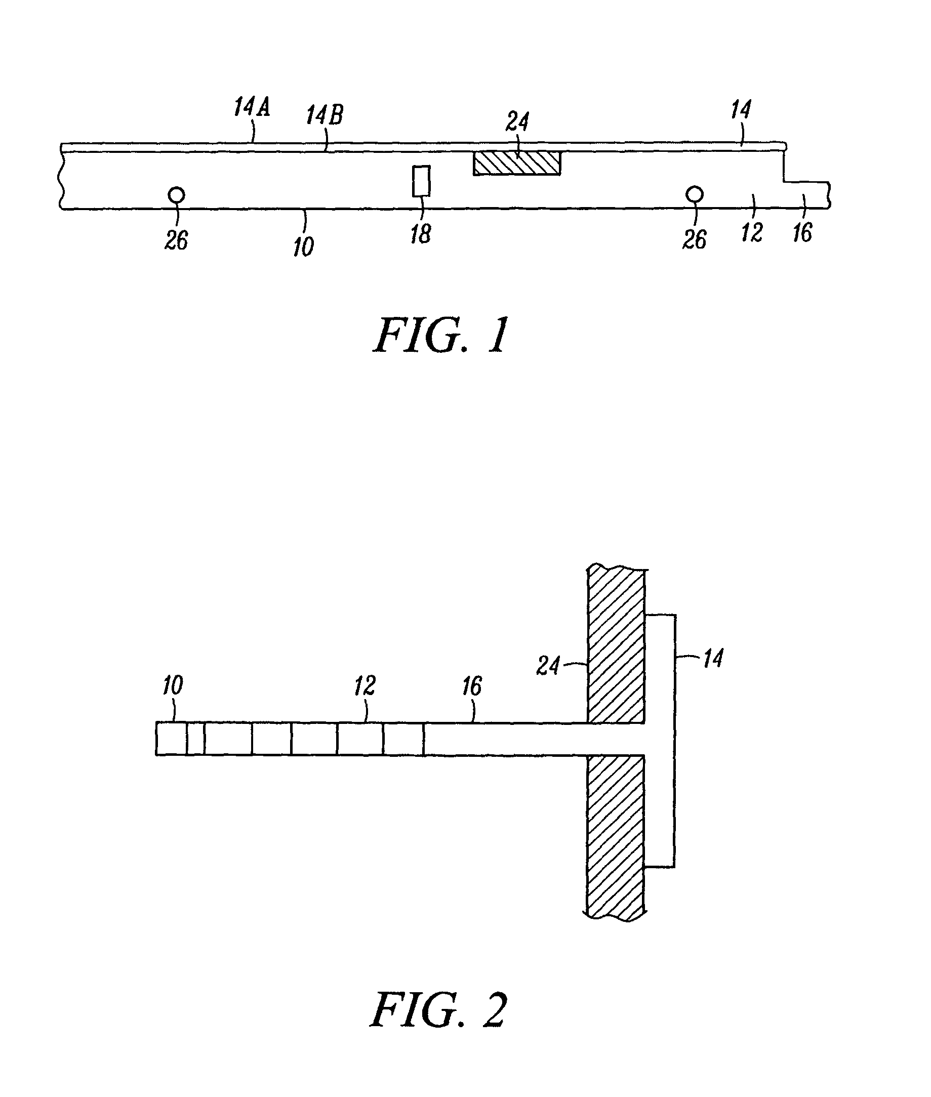
[0033]Referring now to the drawing, there is illustrated in FIGS. 1 and 2 a typical T bar grid support 10 of the type often used in ceiling grid arrays. The T bar grid support has an upright body member 12 and pair of side flanges 14. A connector portion 16, shown schematically in FIG. 1 and in detail in FIG. 15, extend from each of the ends of the upright body member 12 and are used to insert into apertures such as aperture 18 in the upright body member 12 of adjacent T bar grid supports extending at right angles. The lower surface 14a of the side flanges 14 are visible from the area 20 of the room in which the T bar grid and ceiling is installed. The area 22 above the T bar may be an attic or other open space above the ceiling. Ceiling tiles 24 rest on the upper surface 14b of flanges 14. The T bars such as T bar 14 are often aligned in a matrix or grid spaced in 12 inch spacing or multiples of 12 inch spacing. The upright body member 12 is often supplied with apertures 26 to whic...


PUM


Abstract

A ceiling mounted lighting fixture for insertion in a ceiling grid wherein the source of artificial light is a plurality of light emitting diodes.

Description

BACKGROUND OF THE INVENTION[0001]1. Field of the Invention[0002]This invention relates to the artificial lighting field and more particularly to a ceiling mounted lighting fixture adapted to mount in a standard ceiling grid and utilizing LED as the source of the artificial lights.[0003]2. Description of the Prior Art[0004]Many types of lighting fixtures adapted to be mounted on ceilings of residential, commercial and industrial facilities have been utilized in the past. Such lighting fixtures have included hanging chandeliers, fixtures attached to the ceiling, track lights and the like. Incandescent bulbs or fluorescent bulbs have generally been utilized in such fixtures to provide the source of the artificial light.[0005]Many ceilings in residential, commercial and industrial type buildings have included ceiling tiles of various materials and configurations. The tiles were generally arrayed in a standardized rectilinear matrix or grid often in a T bar grid having basic dimensions s...

Claims


Application Information

Patent Timeline
IPC IPC(8): F21S8/00F21V29/00
CPCF21S8/026F21V21/048E04B9/006F21V29/75F21Y2101/02F21V29/763F21Y2115/10
Inventor ESMAILZADEH, ASHKANESMAILZADEH, ARASH
Owner ESMAILZADEH ASHKAN
Why Eureka
Try Eureka