

Cutting insert and holder for rotating applications
a cutting insert and rotating technology, applied in the field of metal working operations, can solve the problems of extending the tool life of cutting inserts, affecting the cutting accuracy of cutting inserts, and affecting the cutting accuracy of cutting inserts, and achieve the effect of flexible radial expansion of the hoop
- Summary
- Abstract
- Description
- Claims
- Application Information
AI Technical Summary
Benefits of technology
Problems solved by technology
Method used
Image

Examples
Embodiment Construction
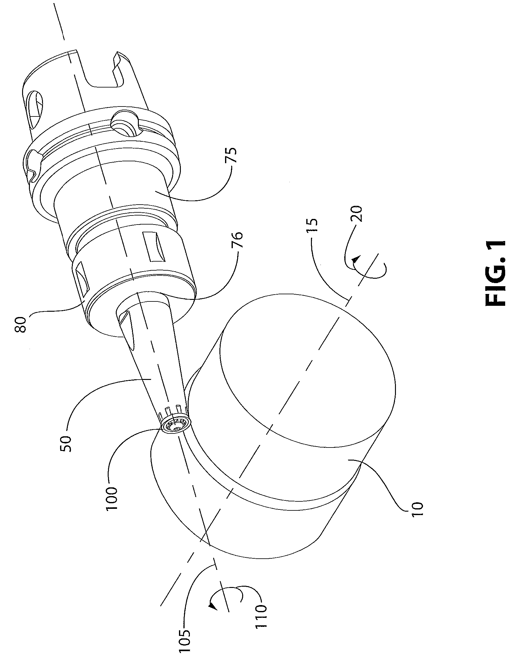
[0026]FIG. 1 illustrates a workpiece 10 rotating about the centerline 15 in a direction indicated by arrow 20 wherein, for example, the workpiece 10 is mounted upon a lathe. A toolholder 50 has mounted thereupon a cutting insert 100. The cutting insert 100 has a central axis 105. The insert 100 is secured to the toolholder 50 in a non-rotatable fashion such that rotation of the toolholder 50 is translated directly to the rotation of the cutting insert 100. As one example, the insert 100 and the toolholder 50 may rotate in a direction illustrated by arrow 110. The toolholder 50 may be secured within an adapter 75, which is mounted to a spindle, and which then would be mounted to a machine tool capable of rotating the adapter 75 in the desired direction and at the desired predetermined rotational speed. The toolholder 50 may be secured within the adapter using any number of techniques known to those skilled in the art of rotary tools. However, as illustrated in FIG. 1, the adapter 75 ...
PUM
| Property | Measurement | Unit |
|---|---|---|
| clearance angle | aaaaa | aaaaa |
| angle | aaaaa | aaaaa |
| angle | aaaaa | aaaaa |
Abstract
Description
Claims
Application Information