
Network system

a network system and network technology, applied in the field of network systems, can solve problems such as troublesome setting operation and difficulty in realization

Inactive Publication Date: 2013-06-18
SONY CORP
View PDF28 Cites 0 Cited by
  • Summary
  • Abstract
  • Description
  • Claims
  • Application Information

AI Technical Summary

Benefits of technology

[0038]According to the invention, only in case of a combination of the router and the terminal apparatus which has been registered in the database provided for an Internet service provider, the connection is permitted to the network such as a homenetwork or the like. The user does not need to set the router by himself and can easily allow the terminal apparatus to participate newly in the network such as a homenetwork or the like. It is also possible to prevent an unregistered terminal apparatus from being connected to the network such as a homenetwork or the like, so that the security of the network can be improved.
[0042]the router reads out the identifier, thereby allowing a link between the router and the terminal apparatus specified by the identifier to be established.
[0064]According to the invention, the recording medium is loaded into the router and the router reads out the identifier on the recording medium, so that the authentication for allowing the router and the terminal apparatus which is specified by the identifier to communicate can be performed. Therefore, the user does not need to execute the troublesome operation such as setting of the router or the like.

Problems solved by technology

However, if a network in the home does not exist, it is difficult to realize, such a request.
Although the setting of routing of the router is performed by the user, since the setting operation is technical and expert, when the user newly connects a terminal apparatus, it is necessary to execute the troublesome setting operation.
However, such a homenetwork depends on the provided firewall and the homenetwork does not become open, so that there is a problem such that it becomes an obstacle in case of developing a variety of kinds of applications.

Method used


Image

  • Network system
  • Network system
  • Network system

Examples


first embodiment

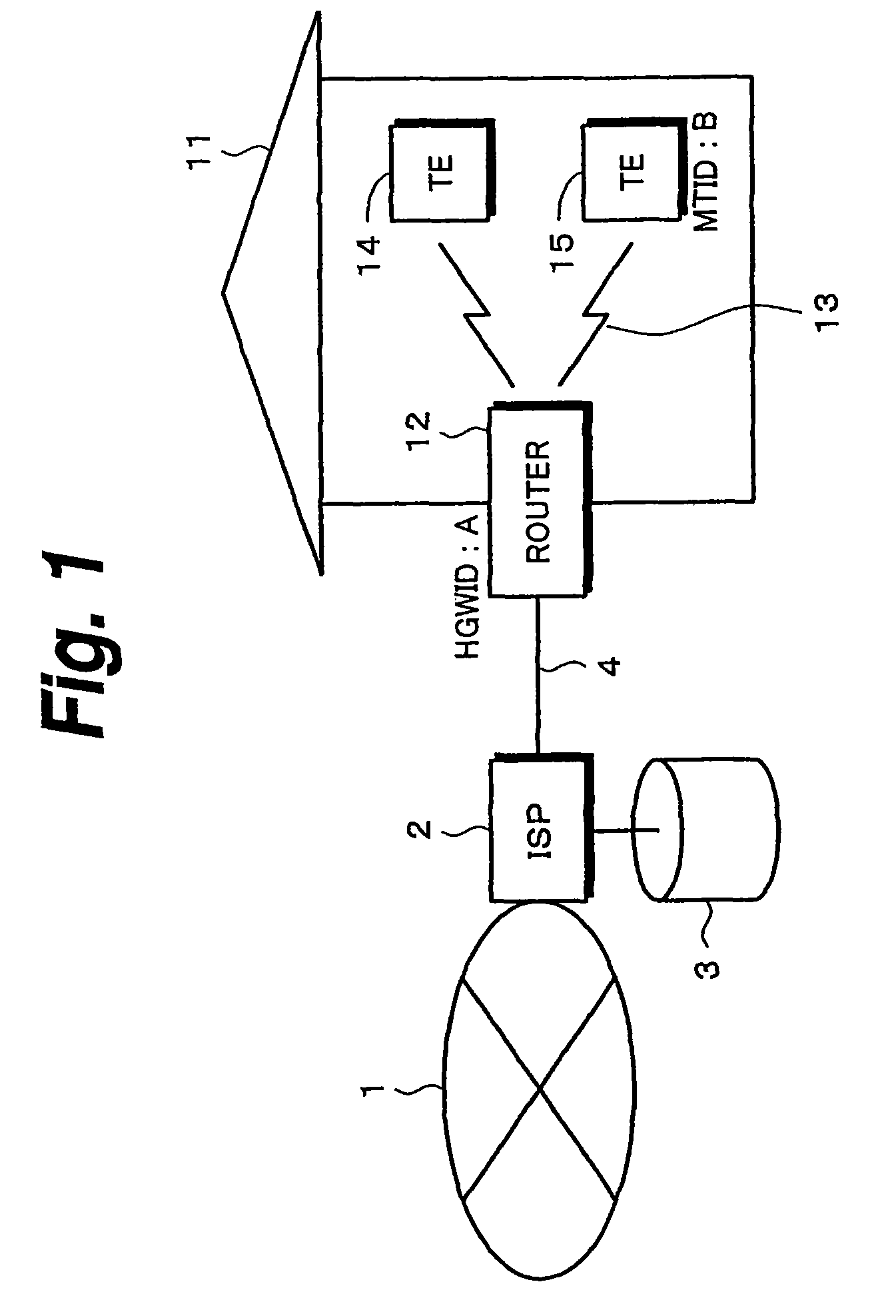
[0096]An embodiment of the invention will be described hereinbelow. FIG. 1 shows an example of a system of the first embodiment of the invention. Reference numeral 1 denotes an Internet; 2 indicates an ISP (Internet Service Provider) connected to the Internet 1. The ISP 2 has a mail server, a DNS (Domain Name System) server, a Proxy server, and the like, provides an ordinary Internet connecting function, and has a database 3 for authentication.

[0097]Reference numeral 11 denotes a home; and 12 indicates a home gateway, for example, a router. The ISP 2 and router 12 are connected by a bidirectional access line 4 such as ISDN (Integrated Services Digital Network) line, dedicated line, xDSL (x Digital Subscriber Line) like an ADSL (Asymmetric Digital Subscriber Line) or the like, optical fiber, or the like. In case of using the ISDN line as a bidirectional access line 4, a DSU (Digital Service Unit) (not shown) and a TA (Terminal Adapter) if necessary are inserted between the router 12 ...

second embodiment

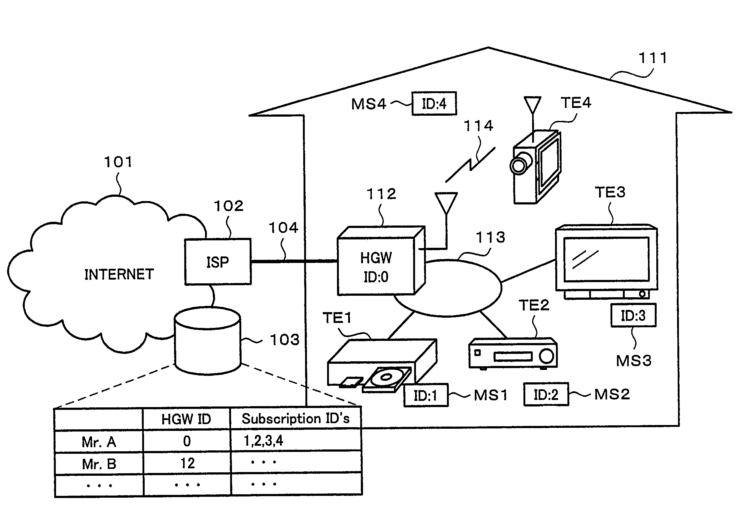
[0112]FIG. 4 shows an example of a system according to the second embodiment of the invention. Reference numeral 101 denotes an Internet and 102 indicates an ISP (Internet Service Provider) serving as a server connected to the Internet 101. The ISP 102 has a mail server, a DNS (Domain Name System) server, a Proxy server, and the like, provides an ordinary Internet connecting function, and has a database 103 for authentication.

[0113]Reference numeral 111 denotes a home; and 112 indicates a home gateway, for example, a router. The ISP 102 and router 112 are connected by a bidirectional access line 104 such as ISDN (Integrated Services Digital Network) line, dedicated line, xDSL (x Digital Subscriber Line) like an ADSL (Asymmetric Digital Subscriber Line) or the like, optical fiber, or the like. In case of using the ISDN as a bidirectional access line 104, a DSU (Digital Service Unit) (not shown) and a TA (Terminal Adapter) if necessary are inserted between the router 112 and the ISDN....


PUM


Abstract

MTID of a terminal apparatus is preliminarily registered into a database of an ISP. In step S2, when a power source of the terminal apparatus is turned on first, (MTID=B) is transmitted from the terminal apparatus to a router. A transmission signal is received by the router and (HGWID=A, MTID=B) is transmitted from the router to the ISP. If (HGWID=A, MTID=B) has been registered in the database, the ISP transmits a permission message in step S5. In step S6, an IP address for a new terminal apparatus is allocated and the new terminal apparatus can participate in a homenetwork. If (HGWID=A, MTID=B) is not registered, a refusal message is sent to the router.

Description

[0001]This is a divisional of U.S. application Ser. No. 10 / 276,627, filed Nov. 18, 2002, now U.S. Pat. No. 7,792,127 which is a national stage filing under 35 U.S.C. §371 of PCT / JP02 / 02581, filed on Mar. 19, 2002, and which claims priority to JP 2001-078740, filed on Mar. 19, 2001, JP 2001-078741, filed on Mar. 19, 2001, and JP 2001-078742, filed on Mar. 19, 2001, all of which are incorporated herein by reference in their entireties.TECHNICAL FIELD[0002]The invention relates to a network system, a connecting apparatus, a connecting method, a network, a router, a terminal apparatus, a communicating method, a program, and a recording medium which can be applied to a case of connecting the network in a home to the Internet.BACKGROUND ART[0003]Contents transmitted into a home via the Internet is usually sent to a personal computer. Compression music data, image data, and the like which were downloaded are stored into the personal computer. The user tries to reproduce those contents whic...

Claims


Application Information

Patent Timeline
Patent Type & Authority Patents(United States)
IPC IPC(8): H04L12/28H04L29/06H04L29/08H04L29/12
CPCH04L12/2898H04L29/06H04L29/12216H04L61/2015H04L63/0807H04L63/101H04N21/4126H04W12/06H04W12/08H04L67/14H04L12/2803H04L69/329H04L61/5007H04L61/5014H04L12/2809H04L2012/2841H04L9/40
Inventor KIMURA, SHINYASASAKI, TAKAHIRONAKADE, MOTOKIKUNITO, YOSHIYUKIHOKIMOTO, AKIHIROOKA, MAKOTOMATSUYAMA, SHINAKOSHIONOZAKI, ATSUSHI
Owner SONY CORP
Learn More