Tissue removal tools and methods of use

a technology of tissue removal and tools, applied in the field of tissue removal tools and methods of use, can solve the problems of reducing the hydraulic pressure affecting the function of the internal disc,

Active Publication Date: 2013-06-25
SPINAL ELEMENTS INC
View PDF188 Cites 51 Cited by
  • Summary
  • Abstract
  • Description
  • Claims
  • Application Information

AI Technical Summary

Problems solved by technology

A major cause of chronic, and often disabling, back pain is disruption or degeneration of an intervertebral disc.
With a loss of water content, the nucleus becomes dehydrated, resulting in a decrease of internal disc hydraulic pressure, and ultimately to a loss of disc height.
This loss of disc height can cause the annulus to buckle, eventually resulting in annular fissures and ruptures.
On the local (or cellular) level, decreased disc height may result in increased pressure in the nucleus pulposus, which can lead to a decrease in normal cell operation and an increase in cell death and disintegration.
In addition, increases in intra-discal pressure may create an unfavorable environment for fluid transfer into the disc, which can cause a further decrease in disc height.
With decreasing height of the disc, the facet joints bear increasing loads and may undergo hypertrophy and degeneration.
Decreased stiffness of the spinal column and increased range of motion resulting from loss of disc height can lead to further instability of the spine, as well as back pain.
There are some significant limitations associated with performing a discectomy with these manual instruments.
The repeated cycles increase the risk of associated nerve damage and the amount of trauma to the surrounding tissue.
Additionally, guidance of the traditional instruments is largely controlled by the dexterity of the surgeon, and even with the most skilled surgeons, repeated precise placement of such instruments is a challenge.
Furthermore, because of the geometric configuration of traditional instruments and the limited work space associated with intervertebral disc procedures, it can be difficult to adequately remove the required amount of material from the nuclear space.
Finally, surgeons typically use traditional instruments without being able to see the tissue being removed.
Thus, the surgeon must be able to distinguish nucleus tissue from annulus tissue and bone tissue by “feel.” Thus, if the surgeon has a difficult time distinguishing between these tissues, serious damage can be done to the annulus of the disc or the vertebral bodies.
However, these methods and techniques also have limitations and risks associated with their use.

Method used


Image

  • Tissue removal tools and methods of use
  • Tissue removal tools and methods of use
  • Tissue removal tools and methods of use

Examples


Embodiment Construction

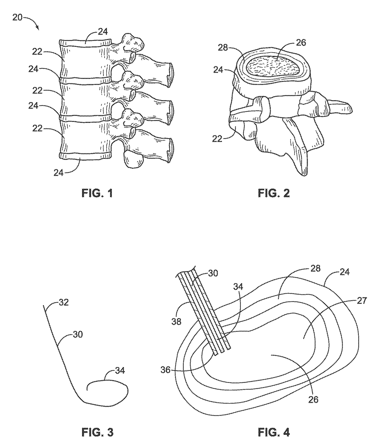
[0073]FIG. 1 illustrates a section of a healthy vertebral (spinal) column, generally designated as 20. Vertebral column 20 includes vertebrae 22 and intervertebral discs 24 separating adjacent vertebrae. Intervertebral discs 24 connect the adjacent vertebra 22 together, providing a joint between the vertebrae that allows movement and flexing of the vertebral column 20. Intervertebral discs 24 also provide a cushion between the adjacent vertebrae 22.

[0074]FIG. 2 illustrates a perspective view of one of the intervertebral discs 24 and an associated inferior vertebra 22. The intervertebral disc 24 includes a nucleus pulposus 26 surrounded by an annulus fibrosus 28. The nucleus pulposus 26 is a gelatinous-like material that provides cushioning between adjacent vertebrae. The annulus fibrosus 28 is made up of tougher fibrous material that contains the nucleus pulposus 26 in the nuclear space.

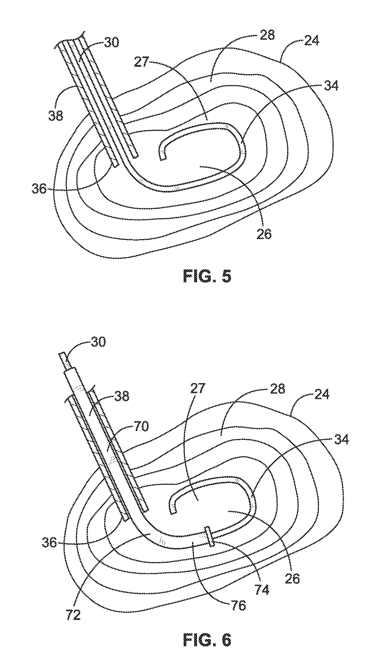
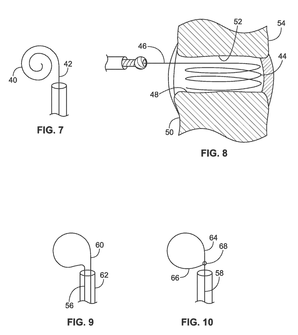
[0075]Turning now to the tissue manipulation members or tools, such as the tissue disruption and ...


PUM


Abstract

Discectomy or disc preparation system that includes a guide member that is changeable from a deployment configuration for insertion into an intervertebral disc space to a deployed configuration upon being deployed into the intervertebral disc. The system also includes at least one tissue manipulator, such as cutting, scraping and extraction elements, that can be moved or tracked longitudinally along the guide member into and through the intervertebral disc space.

Description

[0001]The present application claims the benefit of U.S. Provisional Application Ser. No. 61 / 140,401, filed Dec. 23, 2008, which is incorporated herein by reference.FIELD OF THE INVENTION[0002]The present invention generally relates to apparatus and methods employed in minimally invasive surgical procedures to cut and remove tissue from a patient and, more particularly, to apparatus and methods that may be utilized in a minimally invasive, e.g. endoscopic, surgical procedure to cut and remove tissue from an intervertebral disc.BACKGROUND OF THE INVENTION[0003]A major cause of chronic, and often disabling, back pain is disruption or degeneration of an intervertebral disc. The spine is comprised of bony vertebrae separated by intervertebral discs. Each intervertebral disc connects adjacent vertebrae and forms a joint that allows movement of the vertebral column. An intervertebral disc is generally divided into two regions: the nucleus pulposus and the annulus fibrosus. The nucleus pul...

Claims


Application Information

Patent Timeline
Patent Type & Authority Patents(United States)
IPC IPC(8): A61F2/44
CPCA61B17/32002A61B17/3205A61B2017/00261A61B2017/320032
Inventor SCHALLER, LAURENT B.GOLDEN, STEVEN S.EMERY, JEFFREY L.LEE, JAMES K.HIROTSUKA, MARK Y.BORG, RUSSELL J.
Owner SPINAL ELEMENTS INC
Why Eureka
Try Eureka