Devices and methods for cutting tissue

a technology of tissue and device, applied in the field of tissue cutting devices and methods, can solve the problems of inconvenient connection between external power supply and operator, inconvenient operation, and distinct disadvantages of each power source, and achieve the effect of preventing unstable fluttering of the shuttle body

Inactive Publication Date: 2012-10-23
MYROMED LLC
View PDF239 Cites 52 Cited by
  • Summary
  • Abstract
  • Description
  • Claims
  • Application Information

AI Technical Summary

Benefits of technology

[0015]Various cutting device driven by various power sources are described herein. In certain variations, a vacuum powered tissue cutting device is provided. In one variation, the device includes a medical device driven by a vacuum source comprising a working end having an operable element, the operable element coupled to a mechanism, such that when the mechanism is driven by the vacuum source movement of a drive shaft actuates the operable element; where the drive shaft is located in a chamber and moveable between a drive stroke and a return stroke; a shuttle body moveable between a forward and return positions, wherein movement between the forward and return positions alternates a fluid path between the chamber and vacuum source so that during application of a vacuum from the vacuum source movement of the shuttle body causes the drive shaft to cycle between the drive stroke and the return stroke; and a linkage coupling the drive shaft to the shuttle body such that as the drive shaft approaches the end of the drive or return stroke the linkage transfers a force to the shuttle body to assist in switching between the forward and return positions and prevents unstable flutter of the shuttle body between the forward and return positions.
[0022]Yet another variation of the devices described herein includes a medical device for use with a supply source. One example includes a working end having an operable element; a motor comprising: a supply port for fluidly coupling to the supply source; a first chamber with a drive piston moveably located therein and having a first drive port and a second drive port on respective ends of the chamber that are fluidly isolated from each other; a second chamber with a shuttle body moveably located therein and capable of switching between a first and second position; such that in the first position the shuttle body fluidly couples the first drive port to the supply port and in the second position the shuttle body fluidly couples the second drive port to the supply port where such alternate coupling results in movement of the drive piston between a drive stroke and a return stroke; a linkage coupling a portion of the drive piston to the shuttle body such that as the drive piston approaches the end of the respective drive and return motion, the linkage transfers a force to the shuttle body to assist in switching between the first and second positions preventing unstable flutter of the shuttle body between the first and second positions; and where the operable element is mechanically coupled to the drive piston such that movement of the drive piston causes actuation of the operating element.

Problems solved by technology

Each of these power sources has distinct disadvantages when used to power a resecting medical device.
For example, when an electric motor is used to provide rotational motion of a cutter, the additional weight of the electric motor may cause operator fatigue.
Wires from an external power supply are inconvenient to make the connections and it is inconvenient to have the wires attached to the device during use.
An electric motor increases the total cost of a device because of the relatively high cost of the motor itself and the cost of a power supply (in the case of an externally powered motor) or the cost of a recharging unit (when rechargeable batteries are used).
The addition of electric motors makes sterilization of the device more difficult, e.g., because of the added mass to the device from the motors.
Additionally, the presence of batteries reduces the sterilization options available to the manufacturer, due to the heat generated by certain sterilization techniques.
The presence of batteries adds potentially toxic chemicals that present additional challenges related to toxicity, sterilization, and device disposal.
When using a manually actuated cutting device, the operator may experience fatigue from repeated actuations.
Additionally, manual actuations can be performed only as quickly as the operator can actuate the cutter via mechanical input through a control and the time required to perform an adequate number of actuations may be excessive.
Electrically-powered microdebriders typically require an expensive capital investment in a power console that is separate from the handpiece.
The capital cost of the power console, handpiece, and disposable blades makes procedures such as a nasal polypectomy and other procedures cost prohibitive in a doctor's clinic setting.
Existing microdebriders are typically built with a handle of the device in line with the shaft of the device, as a result, the handle and the operator's hand may interfere with an endoscope and / or the camera.
This may be disadvantageous when the operator loses sight of the end of the device and accidentally cuts or damages structures that come into contact with it.
As a result of these limitations, it is impractical for Ear, Nose, and Throat physicians to remove nasal and sinus polyps or other tissue in an office or other setting using the current technology.
Therefore, patients are left with the undesirable options of a course of steroid treatments to reduce the size of the polyps (with associated steroid side effects), removal of the polyps in an ambulatory surgery center (cost prohibitive and therefore rarely performed as a stand-alone procedure), or leaving the polyps untreated and dealing with the associated breathing obstruction.

Method used


Image

  • Devices and methods for cutting tissue
  • Devices and methods for cutting tissue
  • Devices and methods for cutting tissue

Examples


Embodiment Construction

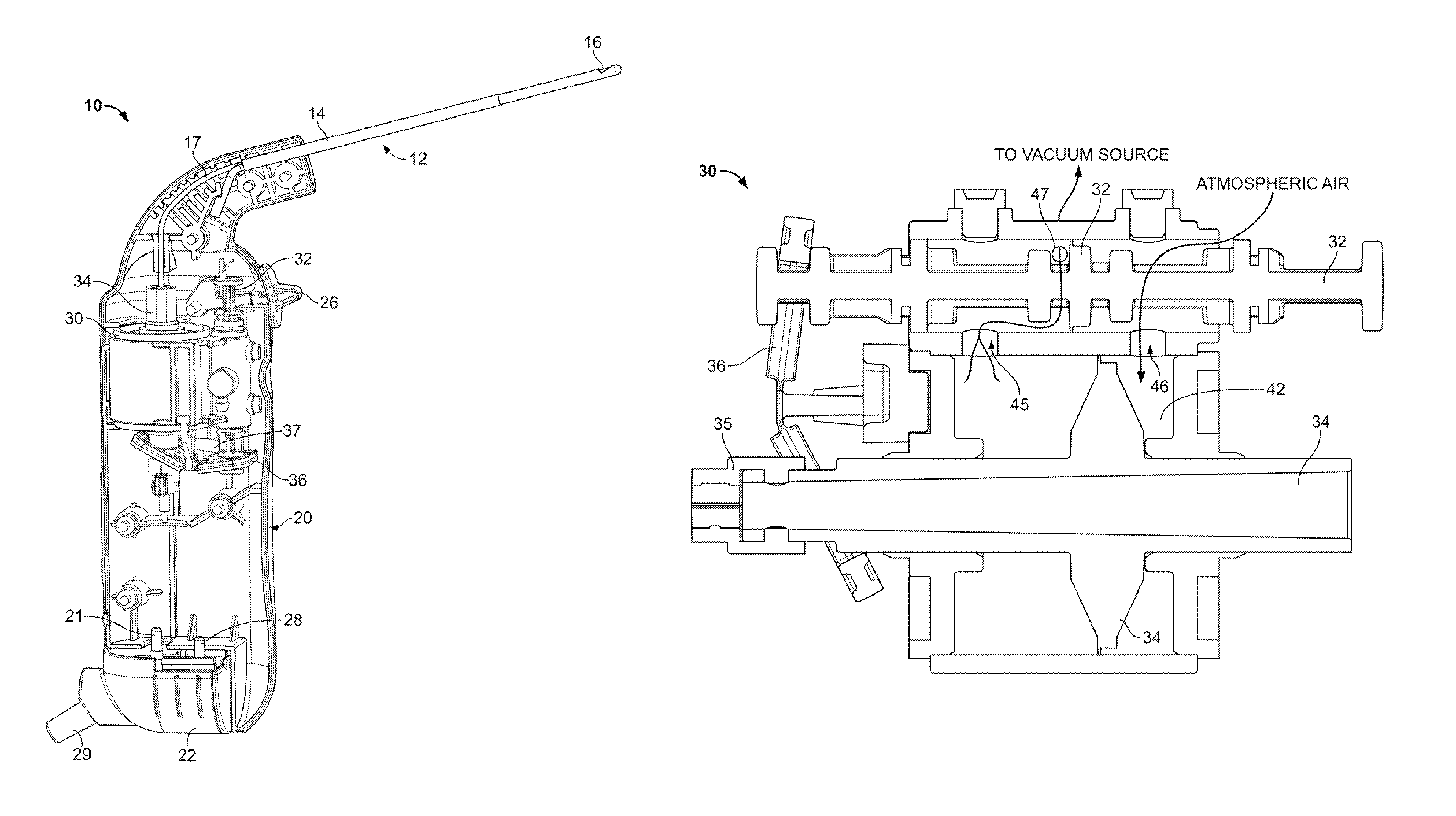
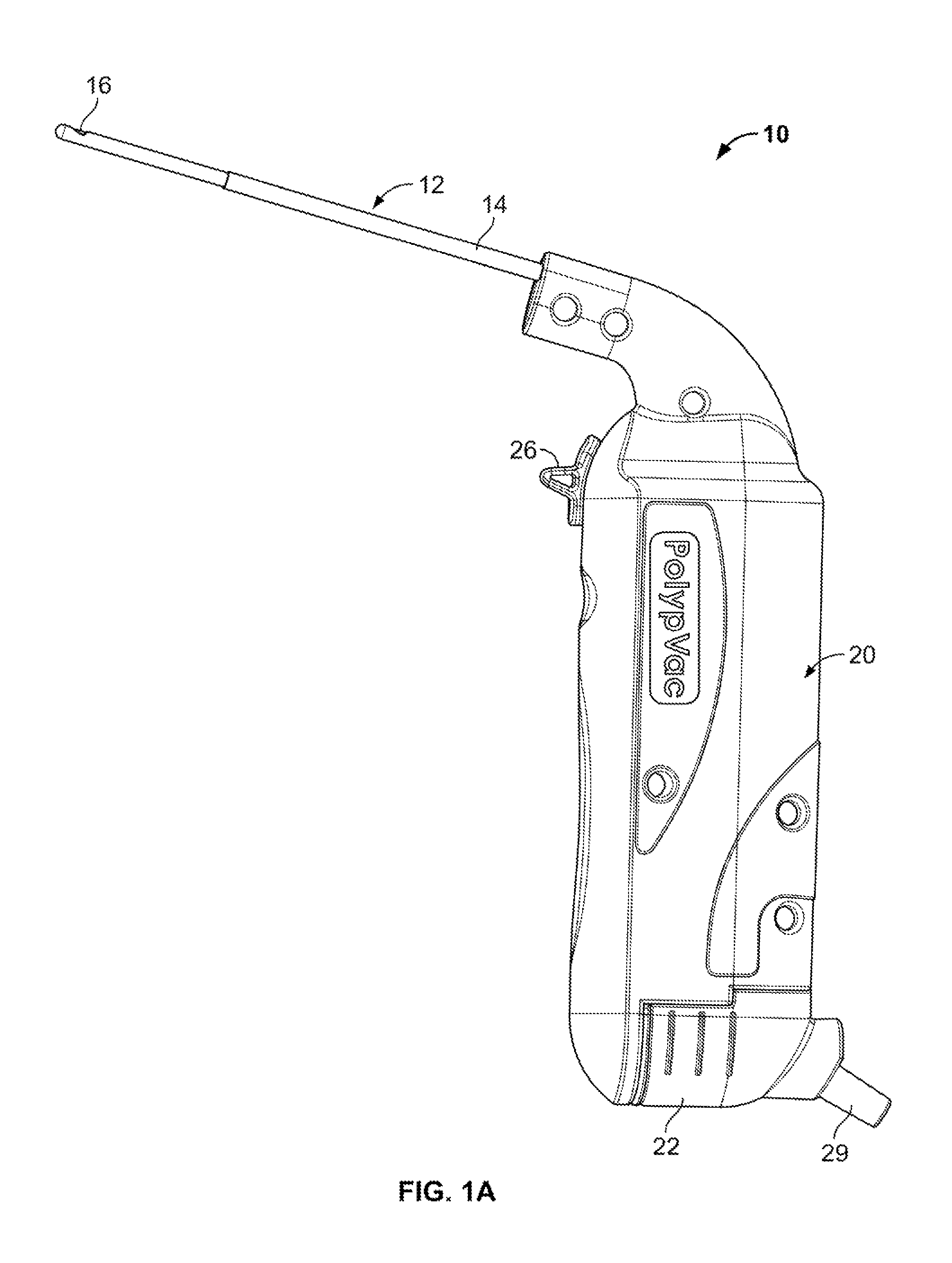
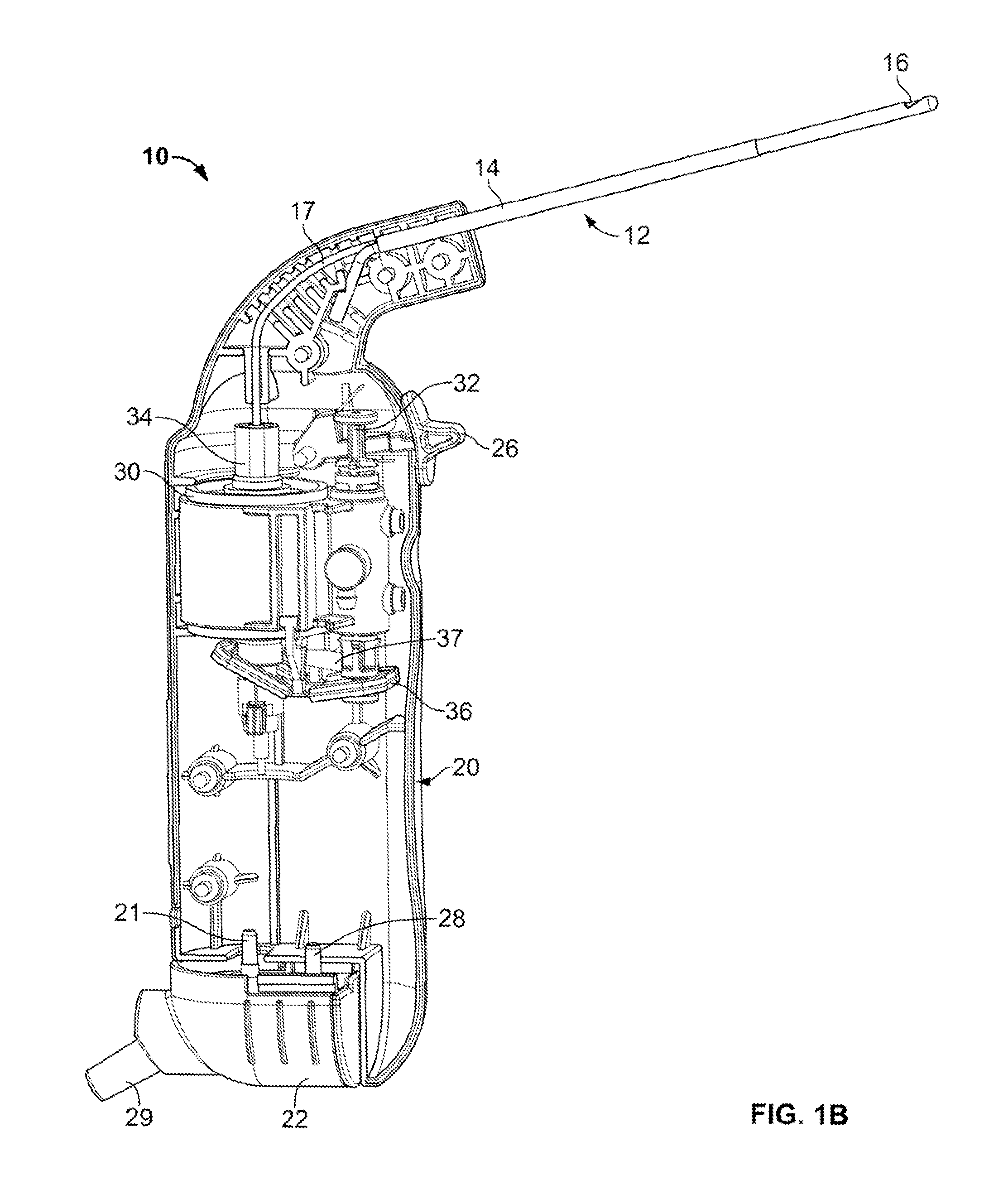
[0056]Variations of the devices are best understood from the detailed description when read in conjunction with the accompanying drawings. It is emphasized that, according to common practice, the various features of the drawings may not be to-scale. On the contrary, the dimensions of the various features may be arbitrarily expanded or reduced for clarity. The drawings are taken for illustrative purposes only and are not intended to define or limit the scope of the claims to that which is shown.

[0057]Various cutting devices and methods for cutting, resecting, incising or excising tissue are described herein. In certain variations a cutting device may include a mechanism or motor driven or powered by a variety of different power sources, e.g., suction from a vacuum source, pneumatic, fluid pressure (e.g. hydraulic), compressed air, battery power or electrical power or gas power or any combination thereof. The mechanism or motor may create a reciprocating or rotational motion output in...


PUM


Abstract

Various medical devices and methods for cutting and / or evacuating tissue are provided. The devices and methods may utilize a reciprocating mechanism or motor powered by suction from a vacuum source. The medical devices and methods may be used on tissue in various regions of a patient's body and for treating various conditions, e.g., for performing a polypectomy or discectomy.

Description

CROSS-REFERENCE TO RELATED APPLICATIONS[0001]The present application is a continuation of U.S. patent application Ser. No. 13 / 174,416 filed Jun. 30, 2011 which claims benefit of priority to U.S. Provisional Patent Application Ser. No. 61 / 360,429 filed Jun. 30, 2010 and U.S. Provisional Patent Application Ser. No. 61 / 377,883 filed Aug. 27, 2010, all of which are incorporated by reference herein in their entirety for all purposes.FIELD OF THE INVENTION[0002]The present devices and methods relate generally to medical devices and methods for cutting and / or evacuating tissue from various regions of a patient's body.BACKGROUND[0003]Many common medical devices perform the function of resecting tissue. Suction, supplied by an external vacuum source is often used to evacuate tissue from the operative site.[0004]Medical devices which cut and evacuate tissue are used in a variety of procedures, including ear, nose, and throat surgery, gynecological surgery, spinal surgery, ophthalmic surgery, ...

Claims


Application Information

Patent Timeline
Patent Type & Authority Patents(United States)
IPC IPC(8): A61B17/32
CPCA61B17/32002A61B2017/00261A61B2017/00269A61B2017/320064A61B2017/320008A61B2017/320028A61B2017/00561
Inventor DUBOIS, BRIAN R.NIELSEN, JAMES T.GORDON, ALEXANDER
Owner MYROMED LLC
Why Eureka
Try Eureka