
Ultrasonic spinal surgery method

a spinal surgery and ultrasonic technology, applied in the field of surgical procedures, can solve the problems of tingling, pain in the back area, weakness, etc., and achieve the effect of improving the quality of li

Active Publication Date: 2008-12-04
MISONIX INC
View PDF9 Cites 55 Cited by
  • Summary
  • Abstract
  • Description
  • Claims
  • Application Information

AI Technical Summary

Benefits of technology

[0010]Another object of the present invention is to provide a surgical discectomy method that is at least partially quicker and easier to carry out than conventional techniques.
[0012]A more particular object of the present invention is to provide such a discectomy method that enhances adhesion of the graft or prosthetic disc to opposing vertebral bone surfaces.
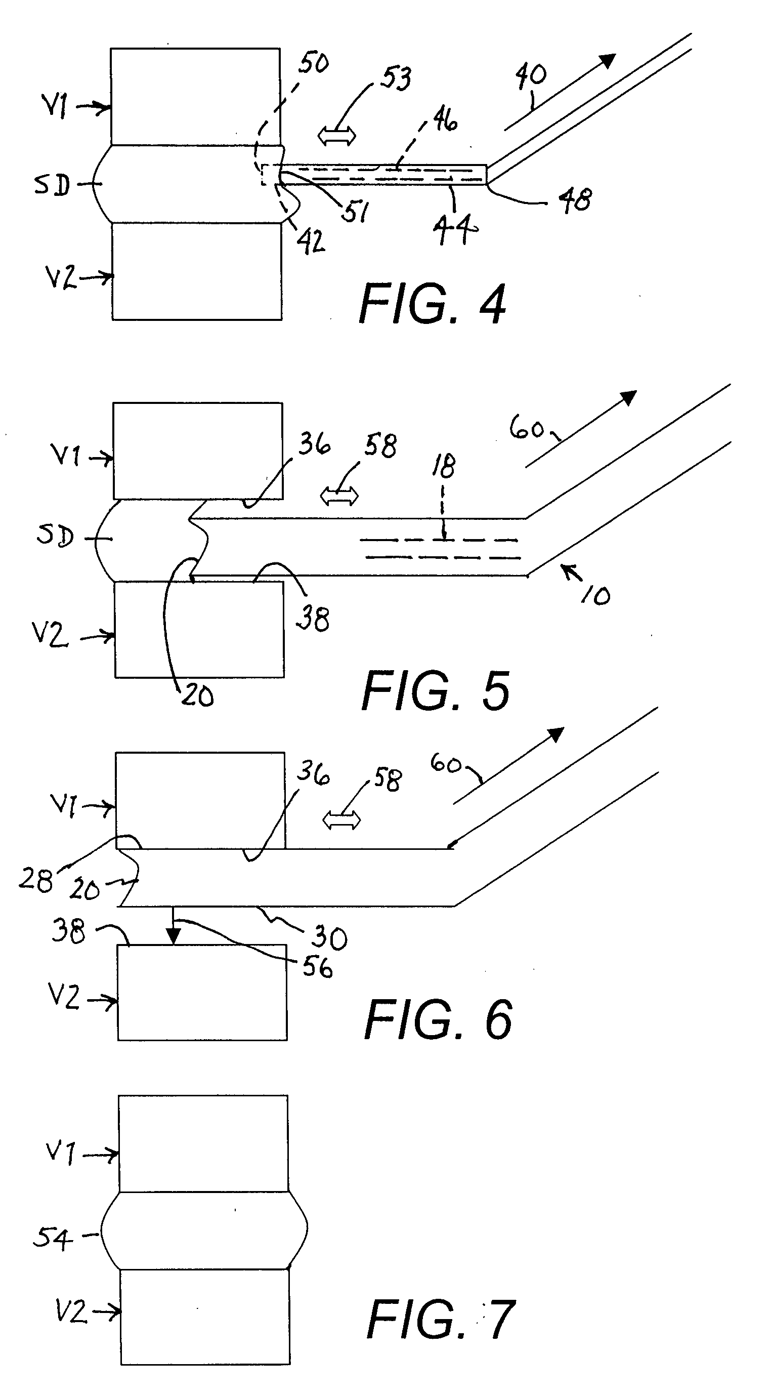
[0017]After removal of the spinal disc, the two vertebrae may be fused to one another. Alternatively, a prosthetic disc or graft may be inserted between the two vertebrae. To implement the latter alternative, the present invention contemplates providing an ultrasonic probe having an operative head with at least one knurled lateral surface, contacting each opposing face of the vertebrae with a knurled lateral surface of the head after at least a portion of the annulus has been removed from between the two vertebrae, and ultrasonically vibrating the head during the contacting of each opposing face of the vertebrae, thereby leveling the opposing faces and providing the opposing faces with textured surfaces. The leveling and texturing of the vertebral surfaces opens access to the blood vessels in the vertebrae and facilitates subsequent growth and attachment of the bone to the material of a prosthetic disc or graft.
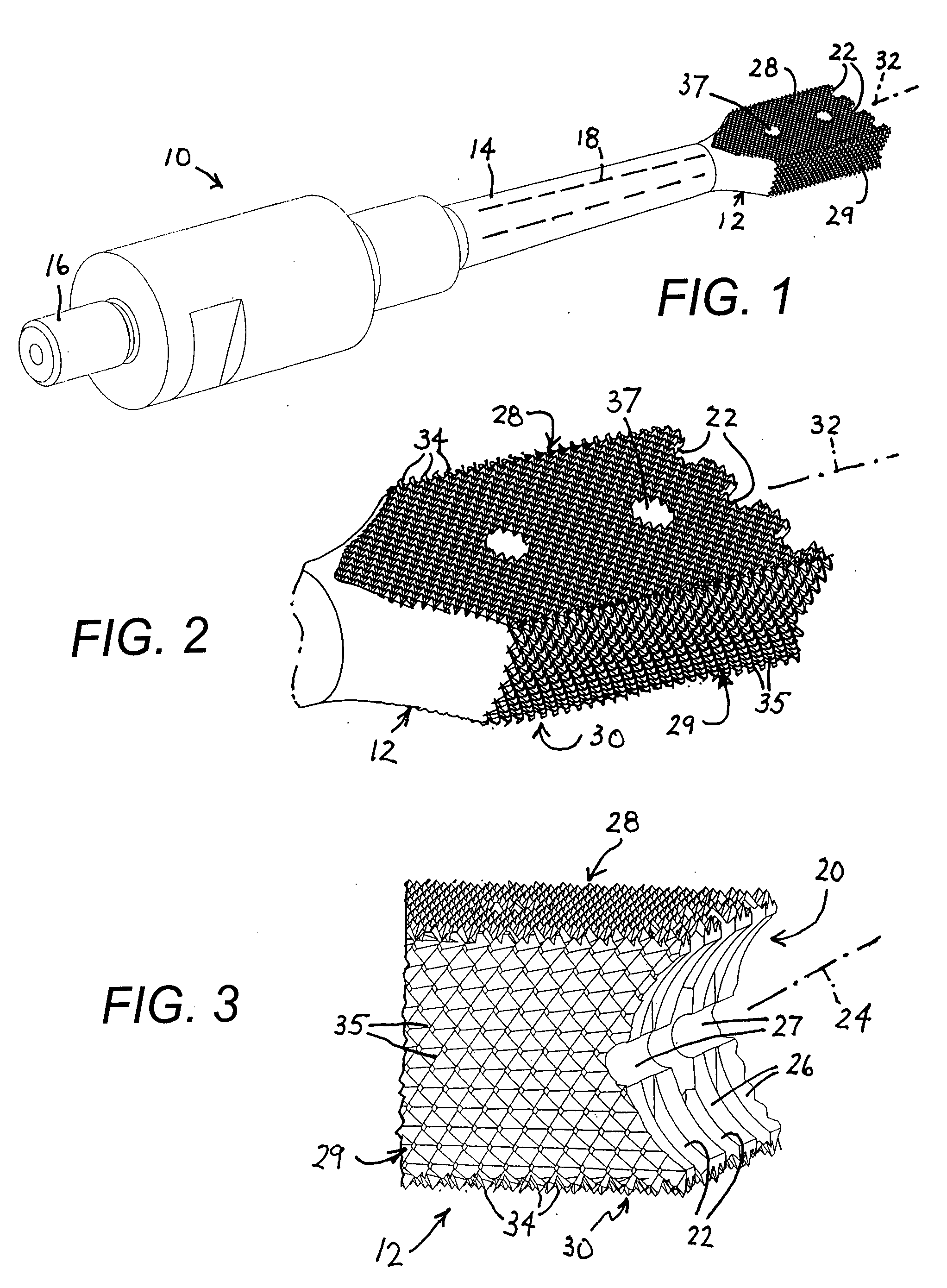
[0018]Pursuant to a more specific feature of the present invention, where the head of the ultrasonic probe is provided with at least two knurled planar surfaces, the contacting of each opposing face of the vertebrae includes contacting the opposing vertebral faces with respective knurled planar surfaces of the head. More specifically, the probe may take the form of an ultrasonic spatula probe, with knurled planar surfaces oriented parallel to a longitudinal axis of the spatula probe, and with the head having a thickness, measured between the opposing knurled planar surfaces, that is less than a distance between the opposing faces of the two vertebrae. In that case, the probe is manipulated to contact the opposing vertebral faces separately. Preferably, but not necessarily, the knurled surfaces of the probe head are at least nearly as wide as the opposing vertebral faces, so that the knurled surfaces need not be moved across the vertebral faces to ensure that the vertebral faces are leveled and textured in their entireties.
[0020]Where the ultrasonic probe has a distal end surface, the removing of the annulus may include contacting the annulus with the distal end surface of the probe, ultrasonically vibrating the head during the contacting of the annulus, thereby fragmenting at least a portion of the annulus, and removing the fragmented annulus from between the two vertebrae. The distal end face of the ultrasonic probe is much larger than the distal end of the ultrasonic tool or cannula, which facilitates removal of the annulus.

Problems solved by technology

Also injury can cause a disc to bulge and press on the nerve root leaving the spinal column, possibly causing extreme pain.
The “bulging” disc can compress or even damage the nerve tissue, and this can cause weakness, tingling, or pain in the back area and into one or both legs.
The most common problem of a discectomy is that there is a chance that another fragment of disc will herniate and cause similar symptoms down the road.

Method used


Image

  • Ultrasonic spinal surgery method
  • Ultrasonic spinal surgery method
  • Ultrasonic spinal surgery method

Examples


Embodiment Construction

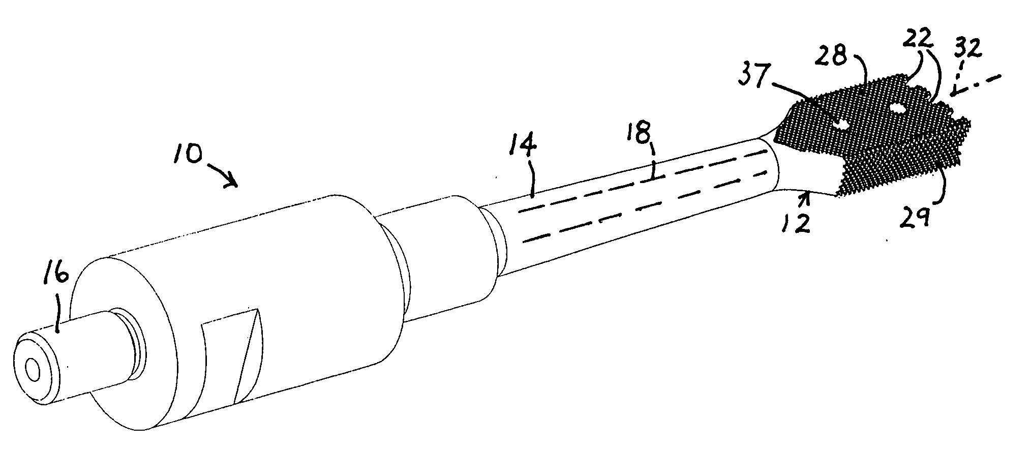
[0045]FIGS. 1-3 depict an ultrasonic probe or instrument 10 with a transversely enlarged but flattened head 12 analogous to a spatula. Probe 10 is similar to probes disclosed in U.S. Patent No. Application Publication No. 2006 / 0241470 by Novak et al., the disclosure of which is hereby incorporated by reference.

[0046]Probe 10 includes a shaft 14 carrying head 12 at a distal end and provided at a proximal end with a connector 16 for coupling the probe to a piezoelectric or magnetostrictive transducer assembly such as that described and illustrated in U.S. Pat. No. 5,371,429 to Manna, the disclosure of which is hereby incorporated by reference. Shaft 14 is formed with a longitudinally extending channel 18 that may be used for conducting an irrigating and cooling liquid (e.g., saline solution, with or without medication) to a surgical site during use of the spatula probe 10.

[0047]As best seen in FIG. 3, head 12 is provided in a distal end face (not separately designated) with a channel,...


PUM


Abstract

In a discectomy method one removes at least a substantial portion of a spinal disc. Thereafter one operates an ultrasonic instrument to level opposing faces of vertebrae on opposite sides of the removed spinal disc. Graft or synthetic disc material is inserted between the vertebrae so that the graft or synthetic disc material is in contact with the leveled opposing faces. In an associated nucleotomy, a cannulated probe is inserted into a spinal disc and used to remove the nucleus pulposus. A synthetic or substitute nucleus material may then be inserted into the evacuated annulus.

Description

BACKGROUND OF THE INVENTION[0001]This invention relates to surgical procedures commonly known as discectomy and nucleotomy.[0002]The spinal column is comprised in part of bones or vertebrae and in part of fibrous discs that are disposed between the vertebrae. The discs normally function as cushions separating the vertebrae. With age, owing to a drying of the disks, the cushioning effect may be reduced. Also injury can cause a disc to bulge and press on the nerve root leaving the spinal column, possibly causing extreme pain.[0003]More specifically, when the outer wall of a disc, called the annulus fibrosis, becomes weakened through age or injury, it may tear allowing the soft inner part of the disc, the nucleus pulposus, to bulge out. This is called disc herniation, disc prolapse, or a slipped or bulging disc. Once the inner disc material extends out past the regular margin of the outer disc wall, it can press against very sensitive nerve tissue in the spine. The “bulging” disc can c...

Claims


Application Information

Patent Timeline
IPC IPC(8): A61B18/18A61H1/00A61N1/00
CPCA61B17/320068A61B17/3417A61B2017/00261A61B2017/320004A61B2017/320008A61B2017/320072A61B2017/349A61B2017/32007A61B2017/320073A61B2017/320069
Inventor DARIAN, ALEXANDER L.VOIC, DANMANNA, RONALD R.
Owner MISONIX INC
Learn More