Display device

a display device and display technology, applied in the field of directviewing display devices, can solve problems such as visible joints between the plurality of display devices

Active Publication Date: 2013-06-25
SHARP KK
View PDF9 Cites 27 Cited by
  • Summary
  • Abstract
  • Description
  • Claims
  • Application Information

AI Technical Summary

Benefits of technology

[0029]According to the present invention, there is provided a direct-viewing type display device which can display a jointless image even when tiled in two directions with a plurality of display devices.

Problems solved by technology

However, using the tiling technique has a problem of visible joints between the plurality of display devices.
This problem is not limited to liquid crystal display devices, but is a problem common to direct-viewing type display devices, e.g., PDPs, organic EL display devices, and electrophoresis display devices.

Method used


Image

  • Display device
  • Display device
  • Display device

Examples


Embodiment Construction

[0050]Hereinafter, an embodiment of the present invention will be described with reference to the drawings. However, the present invention is not limited to the illustrated embodiment.

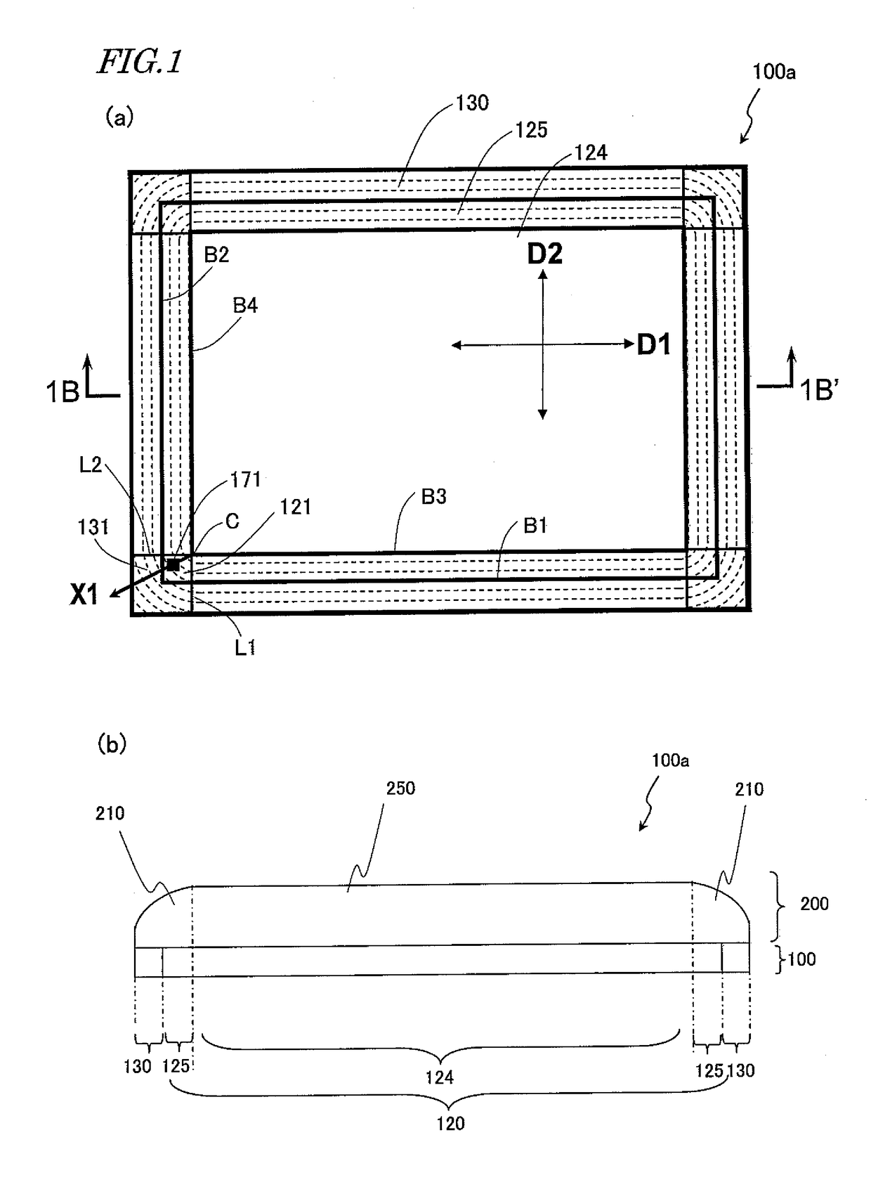
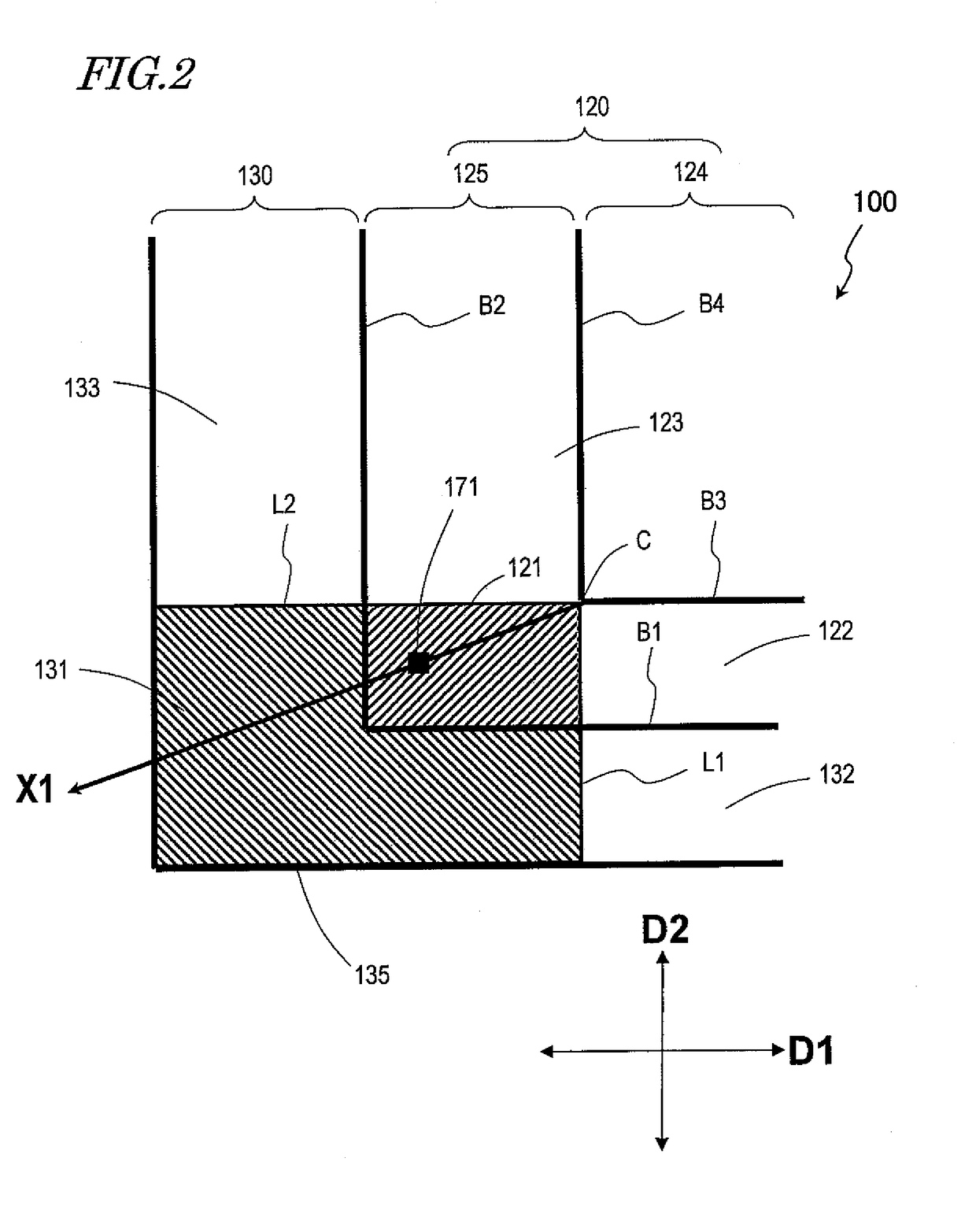
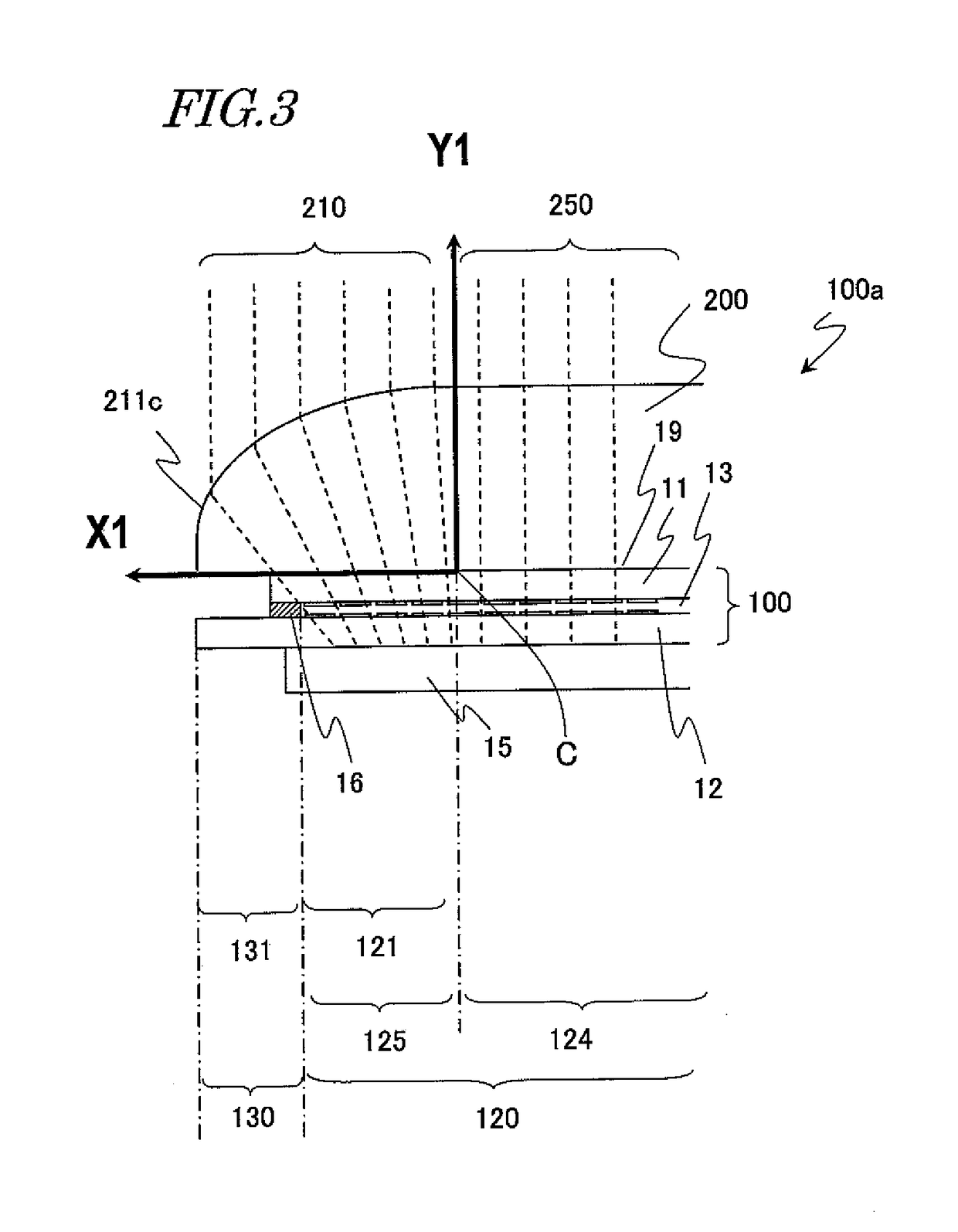
[0051]FIG. 1 schematically shows a direct-viewing type liquid crystal display device 100a according to an embodiment of the present invention. FIG. 1(a) is a schematic upper plan view of the liquid crystal display device 100a as seen from the viewer's side, and FIG. 1(b) is a schematic cross-sectional view along line 1B-1B′ in FIG. 1(a).

[0052]As shown in FIGS. 1(a) and (b), the liquid crystal display device 100a includes a liquid crystal display panel 100 and a light-transmitting cover 200 which is provided on the viewer's side of the liquid crystal display panel 100. The liquid crystal display panel 100 includes a display region 120 in which a plurality of pixels are arranged in a matrix array having rows and columns, and a frame region 130 provided outside the display region 120. The display region 1...


PUM


Abstract

A direct-viewing type display device 100a includes a display panel 100 having a display region 120 including pixels arrayed in a row direction and a column direction and a frame region 130 provided outside the display region, such that a first border line B1 and a second border line B2 exist between the display region and the frame region; and a light-transmitting cover 200 disposed on the viewer's side. The display region includes a peripheral display region 125 and a central display region 124; a third border line B3 and a fourth border line B4 exist between the peripheral display region and the central display region; the peripheral display region includes a first peripheral display section 121; the light-transmitting cover includes a lens portion disposed over the peripheral display region and the frame region; and the lens portion refracts light going out from a pixel 171 within the first peripheral display section in a direction X1 from a point where the third border line and the fourth border line intersect toward the pixel 171. According to the present invention, a display device is provided whose entire frame region including the corner portions can be obscured, such that joints can be obscured in the case of tiling.

Description

TECHNICAL FIELD[0001]The present invention relates to a display device, and more particularly to a direct-viewing type display device.BACKGROUND ART[0002]Conventionally, in television sets and display devices for displaying information, attempts of arraying a plurality of display devices (which may be referred to as a tiling technique) to realize a pseudo large-screen display device are being made. However, using the tiling technique has a problem of visible joints between the plurality of display devices.[0003]This problem will be described by taking a liquid crystal display device for example. A liquid crystal display device includes a liquid crystal display panel, a backlight device, circuits for supplying various electrical signals to the liquid crystal display panel, and a power supply, as well as a housing in which to accommodate these. The liquid crystal display panel includes a pair of glass substrates and a liquid crystal layer provided between them. On one of the pair of g...

Claims


Application Information

Patent Timeline
Patent Type & Authority Patents(United States)
IPC IPC(8): G03B21/56
CPCG02B17/0884G02B27/024G02B27/095G02F1/13336G02F1/133526G02F2001/133331G02F2001/133388H04N2201/0089G02F1/133331G02F1/133388
Inventor WATANABE, HISASHI
Owner SHARP KK
Why Eureka
Try Eureka