

Image capturing lens assembly
a technology of image capturing and lens assembly, which is applied in the field of can solve the problems that the conventional four-piece lens structure cannot meet the requirements of the compact optical image capturing lens assembly
- Summary
- Abstract
- Description
- Claims
- Application Information
AI Technical Summary
Benefits of technology
Problems solved by technology
Method used
Image

Examples
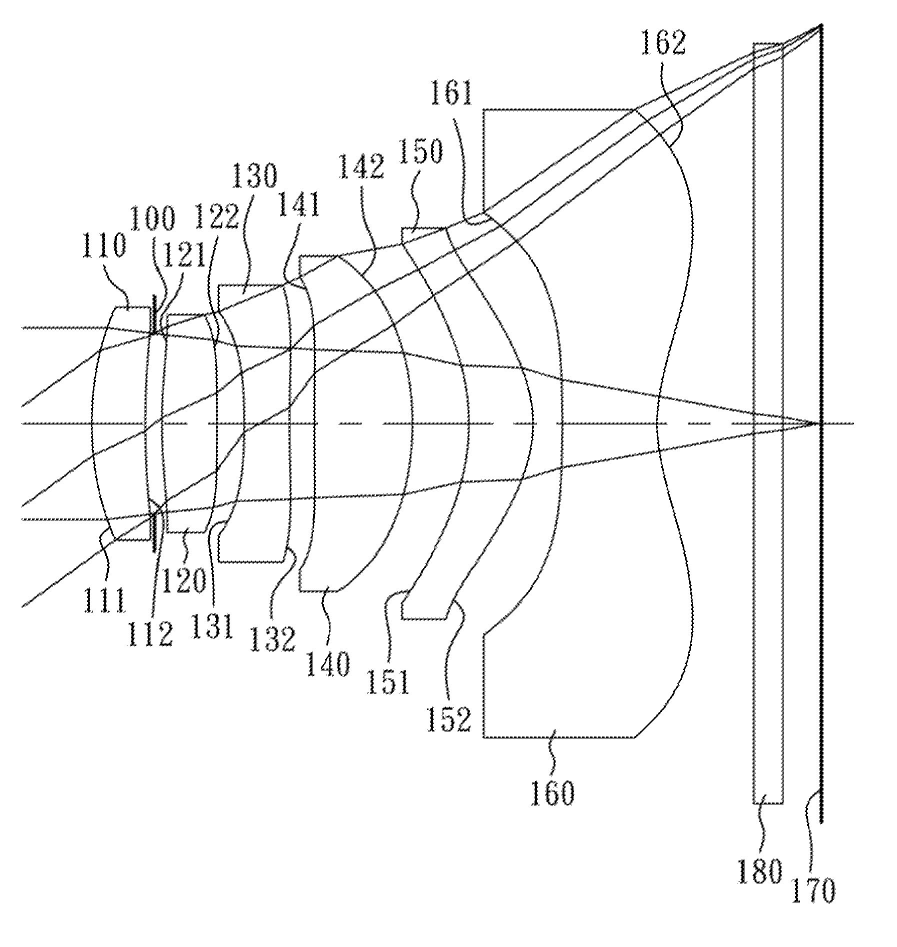
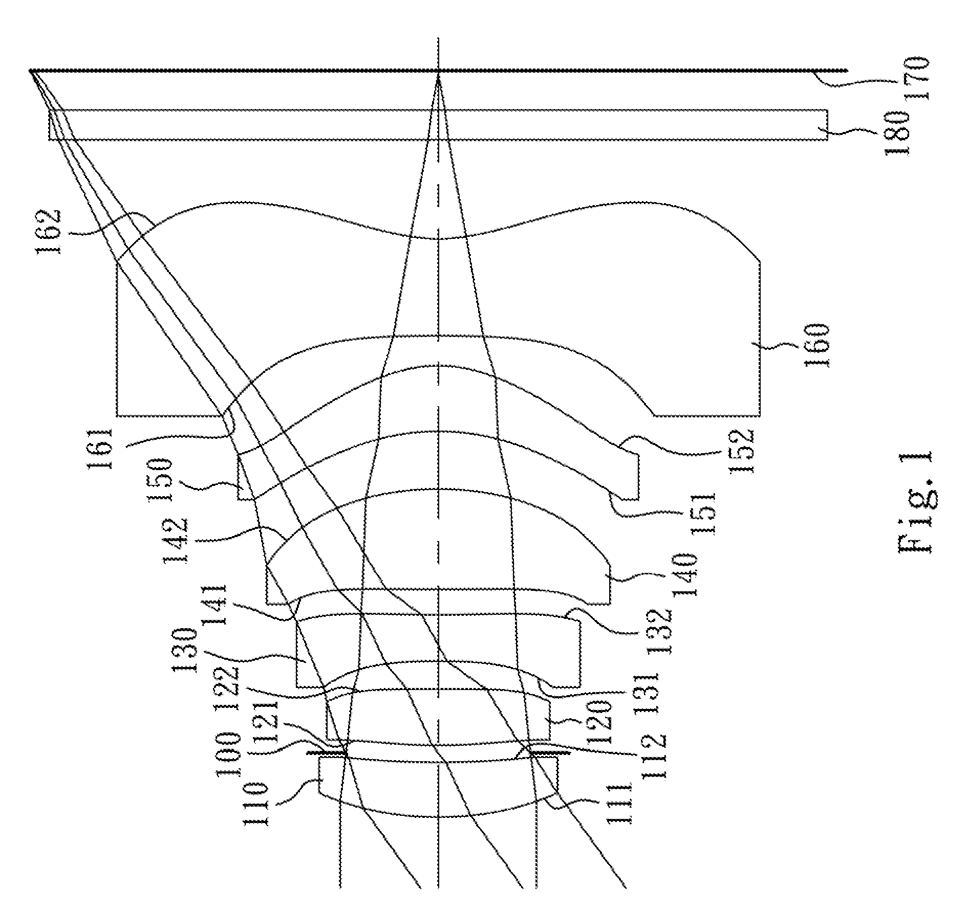
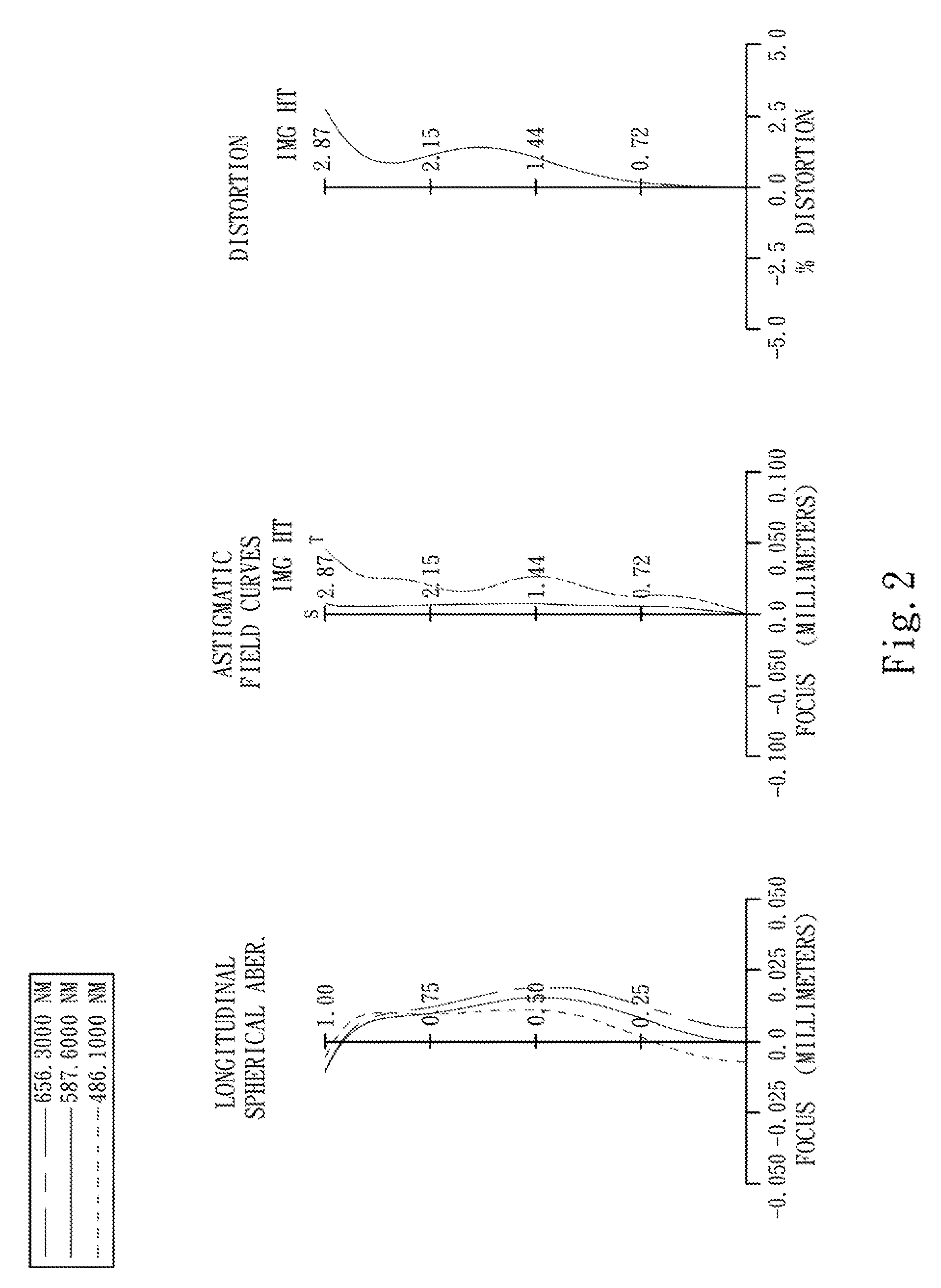
first embodiment
[0067]The equation of the aspheric surface profiles of the aforementioned lens elements of the first embodiment is expressed as follows:
[0068]X(Y)=(Y2 / R) / (1+sqrt(1-(1+k)×(Y / R)2))+∑i(Ai)×(Y′)
[0069]where:
[0070]X is the height of a point on the aspheric surface spaced at a distance Y from the optical axis relative to the tangential plane at the aspheric surface vertex;
[0071]Y is the distance from the point on the curve of the aspheric surface to the optical axis;
[0072]R is the curvature radius of the lens elements;
[0073]k is the conic coefficient; and
[0074]Ai is the i-th aspheric coefficient.
[0075]In the image capturing lens assembly according to the first embodiment, when a focal length of the image capturing lens assembly is f, an f-number of the image capturing lens assembly is Fno, and a half of the maximal field of view is HFOV, these parameters have the following values:
[0076]f=3.87 mm;
[0077]Fno=2.80; and
[0078]HFOV=35.7 degrees.
[0079]In the image capturing lens assembly accor...
second embodiment
[0100]The detailed optical data of the second embodiment are shown in Table 3 and the aspheric surface data are shown in Table 4 below.
[0101]
TABLE 32nd Embodimentf = 3.82 mm, Fno = 2.80, HFOV = 36.2 deg.SurfaceFocal#Curvature RadiusThicknessMaterialIndexAbbe #length0ObjectPlanoInfinity1Ape.Plano−0.090Stop2Lens 1 2.018040 (ASP)0.417Plastic1.51456.83.563−18.011600 (ASP)0.1194Lens 2−28.172900 (ASP)0.339Plastic1.58330.276.715−17.365200 (ASP)0.2316Lens 3 −3.420100 (ASP)0.306Plastic1.63423.8−3.767 8.166700 (ASP)0.1508Lens 4 11.917400 (ASP)0.796Plastic1.54455.93.659 −2.330000 (ASP)0.18010Lens 5 −1.628780 (ASP)0.470Plastic1.54455.93.5911 −0.978890 (ASP)0.39112Lens 6−29.496300 (ASP)0.577Plastic1.54455.9−2.0713 1.181560 (ASP)0.70014IR-filterPlano0.210Glass1.51764.2—15Plano0.28216ImagePlano—Note:Reference wavelength (d-line) is 587.6 nm.
[0102]
TABLE 4Aspheric CoefficientsSurface #234567k =−1.27895E+01−1.00000E+00−1.91450E+01−1.00000E+00−1.00000E+004.78716E+01A4 =1.80790E−01−4.13520E−02−5.24012E...
third embodiment
[0114]The detailed optical data of the third embodiment are shown in Table 5 and the aspheric surface data are shown in Table 6 below.
[0115]
TABLE 53rd Embodimentf = 3.80 mm, Fno = 3.00, HFOV = 36.2 deg.SurfaceFocal#Curvature RadiusThicknessMaterialIndexAbbe #length0ObjectPlanoInfinity1Lens 1 2.533660 (ASP)0.467Plastic1.53055.812.142 3.913500 (ASP)0.1423Lens 2 2.480300 (ASP)0.334Plastic1.53055.85.134 27.208600 (ASP)0.0105Ape.Plano0.150Stop6Lens 3 −5.261000 (ASP)0.250Plastic1.63423.8−4.347 5.864500 (ASP)0.1548Lens 4−55.864500 (ASP)0.549Plastic1.54455.93.689 −1.939770 (ASP)0.66110Lens 5 −1.539920 (ASP)0.491Plastic1.54455.92.7311 −0.840860 (ASP)0.11812Lens 6−53.882600 (ASP)0.619Plastic1.54455.9−1.9013 1.056300 (ASP)0.70014IR-filterPlano0.210Glass1.51764.2—15Plano0.41616ImagePlano—Note:Reference wavelength (d-line) is 587.6 nm.
[0116]
TABLE 6Aspheric CoefficientsSurface #123467k =−2.47599E+01−1.00000E+00−9.77047E+00−1.00000E+00−1.00000E+004.07728E+01A4 =1.88877E−01−2.82714E−02−4.95761E−02−...
PUM
 Abstract
Description
Claims
Application Information