Bipolar secondary battery, method for manufacturing the bipolar secondary battery, bipolar electrode, method for manufacturing the bipolar electrode and assembled battery

a secondary battery and battery assembly technology, applied in the direction of batteries, flat cell grouping, sustainable manufacturing/processing, etc., can solve the problem of short circuit between the positive electrode and the negative electrode, and achieve the effect of suppressing the occurrence of short circui

Active Publication Date: 2013-07-09
NISSAN MOTOR CO LTD
View PDF10 Cites 1 Cited by
  • Summary
  • Abstract
  • Description
  • Claims
  • Application Information

AI Technical Summary

Benefits of technology

[0006]Embodiments of the present invention provide a bipolar secondary battery capable of preventing an internal short circuit in each unit cell thereof.
[0008]With this arrangement, the protrudent portions that are disposed at the end portions of each of the first electrode layer and the second electrode layer are prevented from being opposed in alignment with each other along the separator disposed between the first and second electrode layers. Accordingly, it is possible to suppress occurrence of a short circuit inside each unit cell in the bipolar secondary battery.

Problems solved by technology

The local area of the separator tends to be excessively reduced in thickness or penetrated, thereby causing a short circuit between the positive electrode and the negative electrode.

Method used


Image

  • Bipolar secondary battery, method for manufacturing the bipolar secondary battery, bipolar electrode, method for manufacturing the bipolar electrode and assembled battery
  • Bipolar secondary battery, method for manufacturing the bipolar secondary battery, bipolar electrode, method for manufacturing the bipolar electrode and assembled battery
  • Bipolar secondary battery, method for manufacturing the bipolar secondary battery, bipolar electrode, method for manufacturing the bipolar electrode and assembled battery

Examples


example 1

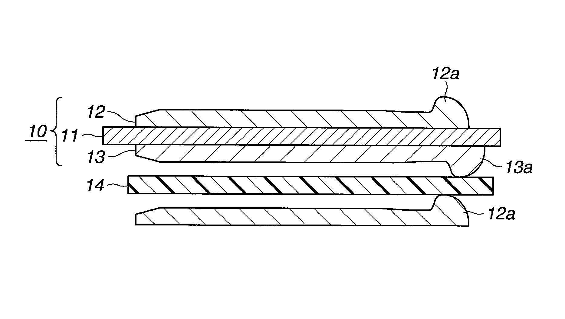
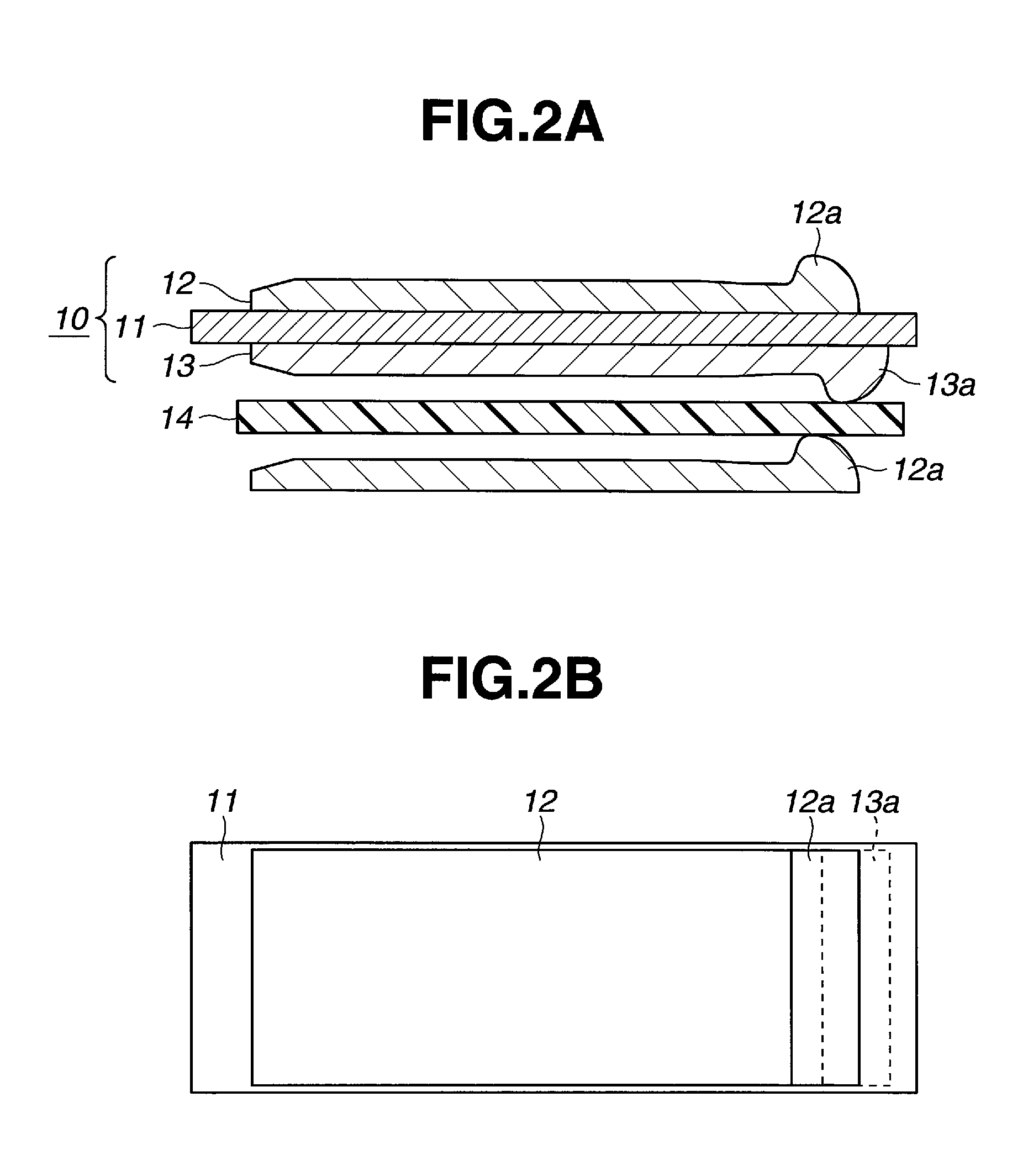
[0159]Upon preparing each of the bipolar electrodes, the positive electrode slurry was applied to a front surface of the current collector so as to reduce the size of the resultant positive electrode by 2.5 mm in the vertical and lateral directions as compared to the negative electrode applied to a rear surface of the current collector.

example 2

[0160]Upon preparing each of the bipolar electrodes, the application of the positive electrode slurry and the application of the negative electrode slurry were started from positions on the opposite surfaces of the current collector that were aligned with each other. The prepared bipolar electrodes were stacked on one another while alternately rotating them by an angle of 180 degrees.

example 3

[0161]Upon preparing each of the bipolar electrodes, after the positive electrode slurry was applied, the negative electrode slurry was applied such that the application start position thereof was disposed on a side of the application termination position of the previously applied positive electrode slurry.


PUM

PropertyMeasurementUnit
lengthaaaaaaaaaa
sizeaaaaaaaaaa
thicknessaaaaaaaaaa

Abstract

A bipolar secondary battery includes a plurality of bipolar electrodes, each including a current collector that has a positive electrode layer on one surface thereof and a negative electrode layer on the opposite surface thereof. A separator is disposed between adjacent two bipolar electrodes such that the positive electrode layer of one bipolar electrode and the negative electrode layer of the adjacent bipolar electrode adjacent are opposed to each other along the length of the separator. The positive electrode layer and the negative electrode layer are formed with protrudent portions disposed at positions offset from each other along a length of the current collector.

Description

CROSS-REFERENCE TO RELATED APPLICATIONS[0001]The present application claims priority from Japanese Patent Application No. 2008-247721, filed Sep. 26, 2008 and Japanese Patent Application No. 2009-133934, filed Jun. 3, 2009, the contents of which are both hereby incorporated by reference in their entirety.TECHNICAL FIELD[0002]The present invention relates to a bipolar secondary battery, a method for manufacturing the bipolar secondary battery, a bipolar electrode, a method for manufacturing the bipolar electrode and an assembled battery.BACKGROUND[0003]A double-pole secondary battery (also called a bipolar secondary battery) includes a plurality of bipolar electrodes that each include a current collector, a positive electrode disposed on one surface of a current collector and a negative electrode disposed on an opposite surface of the current collector. In such a structure of the bipolar electrodes, the plurality of bipolar electrodes are stacked on each other such that the positive ...

Claims


Application Information

Patent Timeline
Patent Type & Authority Patents(United States)
IPC IPC(8): H01M6/46H01M4/82H01M10/18H01M2/10H01M4/02H01M10/04H01M10/052H01M10/0585
CPCH01M10/0418H01M10/044H01M10/052H01M10/0585H01M4/0404Y10T29/49108H01M2004/029Y02E60/122Y02T10/7011Y02E60/10Y02P70/50H01M4/13H01M2220/20Y02T10/70
Inventor SATO, MASANOBUHOSAKA, KENJIHORIE, HIDEAKISHIMOIDA, YOSHIOAOYAGI, MASANORI
Owner NISSAN MOTOR CO LTD
Why Eureka
Try Eureka