
Prismatic battery

a battery and insulating resin technology, applied in the field of prismatic batteries, can solve the problems of low mechanical strength of insulating resin tape, unsatisfactory decrease in battery volume energy density, broken or otherwise damaged, etc., and achieve the effect of increasing the volume energy density of the battery, preventing internal short circuits, and being easy to manufactur

Active Publication Date: 2009-10-06
SANYO ELECTRIC CO LTD
View PDF4 Cites 7 Cited by
  • Summary
  • Abstract
  • Description
  • Claims
  • Application Information

AI Technical Summary

Benefits of technology

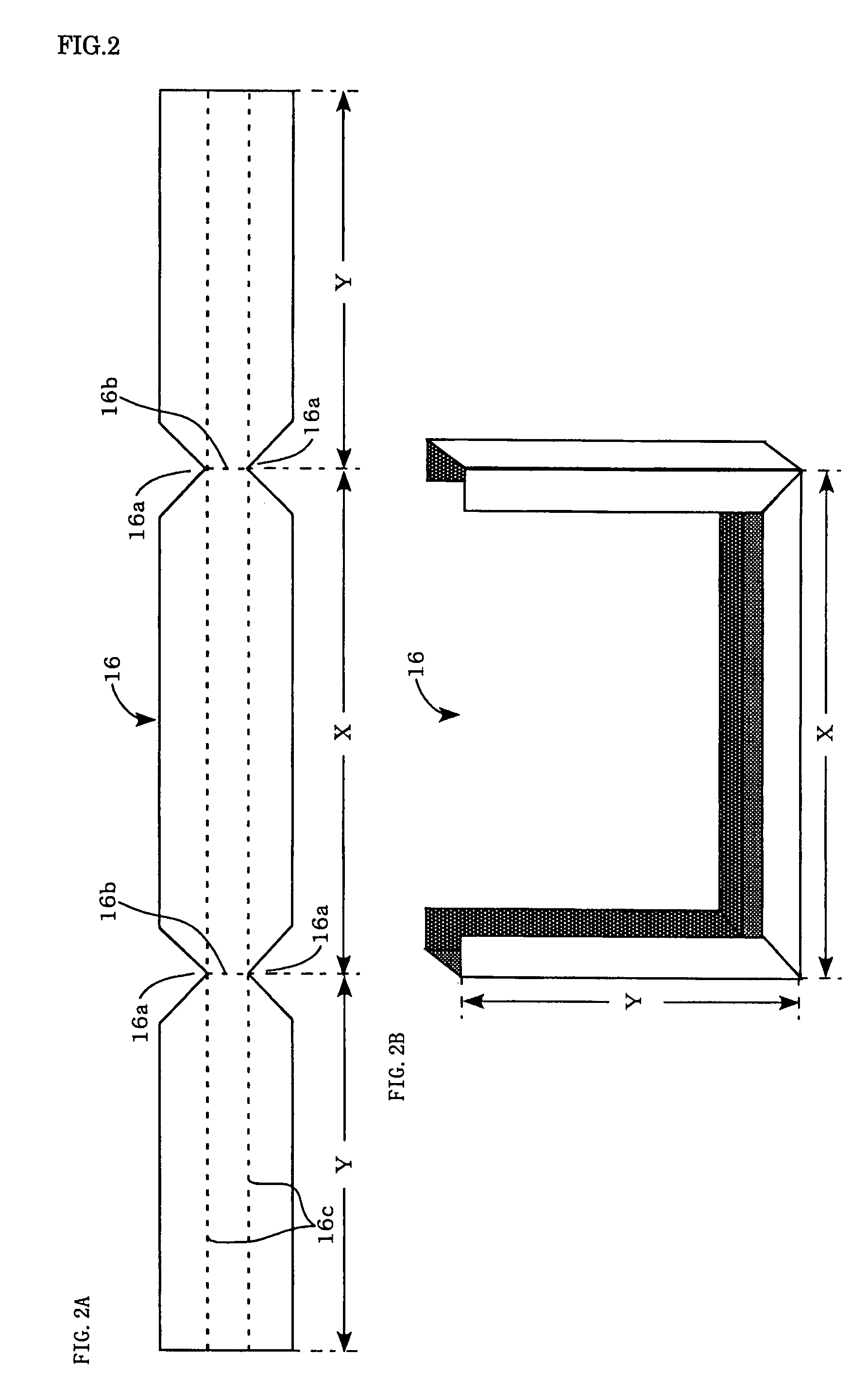
The invention provides a prismatic battery with an electrode group that is covered with an easily manufactured insulating cover, which maintains the battery's volume energy density and prevents an internal short circuit. The insulating frame is made of a resin sheet having an angled U-shaped cross section and outline, which protects the periphery of the electrode group and prevents damage during insertion into the metal outer can. The insulating frame can be bent along two first folding lines and two second folding lines to have an almost angled U-shaped outline. The resin sheet for the insulating frame can be any one of polypropylene, polyethylene, polyphenylene sulfide, polyether ether ketone, and nylon.

Problems solved by technology

However, providing a clearance that is wide enough to prevent an internal short circuit means extra space in the battery, resulting in an undesirable decrease in the battery's volume energy density.
This however causes another problem.
Since the insulating resin tape has low mechanical strength, it may be broken or otherwise damaged when the flattened electrode group 20 provided with this tape is inserted into the metal outer can 27, and as a result, comes in contact with the opening surface of the metal outer can 27.
Furthermore, providing this tape at more positions requires more work.
This molded piece, however, would be large in size, which increases the cost of parts and makes it difficult to have a reduced thickness, thereby lowering the battery's volume energy density.

Method used


Image

  • Prismatic battery
  • Prismatic battery
  • Prismatic battery

Examples


Embodiment Construction

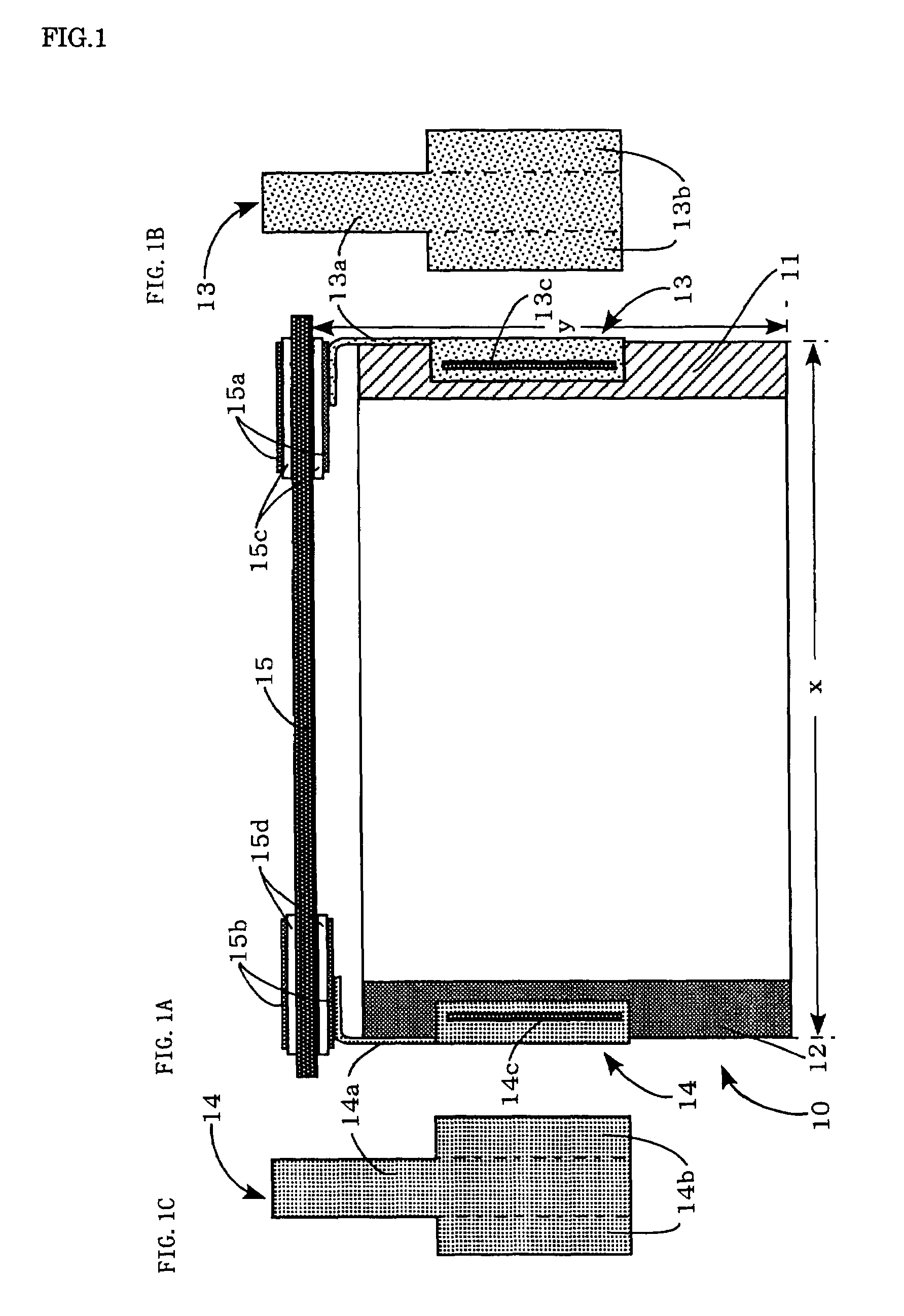
[0022]An exemplary embodiment of the invention will be described with reference to FIGS. 1 through 4. It should be understood that the embodiment is not intended to limit the invention. Various changes and modifications can be made without departing from the spirit and scope of the invention. FIGS. 1A to 1C schematically show an electrode group according to one embodiment of the invention. FIG. 1A is a side view schematically showing the electrode group to which a sealing plate is welded at its upper part. FIG. 1B is a plan view schematically showing a positive electrode current collector. FIG. 1C is a plan view schematically showing a negative electrode current collector. FIGS. 2A and 2B schematically show an insulating frame according to the present embodiment. FIG. 2A is a plan view schematically showing a sheet material to be formed into the insulating frame. FIG. 2B is a perspective view schematically showing the sheet material bent to form the insulating frame. FIG. 3 is a sid...


PUM

PropertyMeasurementUnit
thicknessaaaaaaaaaa
widthaaaaaaaaaa
thicknessaaaaaaaaaa

Abstract

According to an embodiment of the invention, a prismatic battery includes an electrode group 10 contained in a prismatic metal outer can. The electrode group 10 has a positive electrode substrate exposed part 11 at one end and a negative electrode substrate exposed part 12 at the other end. The positive and negative electrode substrate exposed parts 11 and 12 are bundled and welded to positive and negative electrode current collectors 13 and 14, respectively. The positive electrode substrate exposed part 11 and positive electrode current collector 13 and the negative electrode substrate exposed part 12 and negative electrode current collector 14 are covered with an insulating frame 16 having an angled U-shaped cross section and an angled U-shaped outline. It is therefore possible to provide a prismatic battery of a simple structure including an electrode group whose ends are covered with an easily manufactured insulating cover in which the battery's volume energy density is maintained and an internal short circuit is prevented.

Description

BACKGROUND[0001]1. Technical Field[0002]The present invention relates to a prismatic battery, such as a lithium-ion or alkaline battery. More particularly, the invention relates to a prismatic battery including an electrode group contained in a prismatic metal outer can. The electrode group has a positive electrode substrate exposed part at one end and a negative electrode substrate exposed part at the other end.[0003]2. Related Art[0004]Lithium secondary batteries with high energy density (measured in Wh / Kg) have been developed as power sources for cellular phones, notebook computers, compact camcorders, and other mobile electronics and communications equipment, and for electric vehicles (EVs) and hybrid electric vehicles (HEVs). In particular, prismatic batteries have been attracting attention for their high volume energy density (measured in Wh / l).[0005]A typical method for manufacturing such prismatic batteries can be illustrated as follows. JP-A-2004-303500 is an example of rel...

Claims


Application Information

Patent Timeline
Patent Type & Authority Patents(United States)
IPC IPC(8): H01M2/18H01M10/05H01M10/058H01M50/417
CPCH01M2/1653H01M2/18H01M2/0217Y02T10/7011H01M10/052Y02E60/10H01M50/103Y02P70/50H01M50/417H01M50/59H01M50/414H01M50/119H01M50/536H01M10/0587
Inventor YAMAUCHI, YASUHIRONAKANISHI, NAOYANOHMA, TOSHIYUKI
Owner SANYO ELECTRIC CO LTD
Learn More