Techniques for displaying malfunctions of the multifunction printer to users

a multi-function printer and malfunctioning technology, applied in the field of multi-function printers, can solve problems such as user difficulty in finding the right troubleshooting instruction, and achieve the effect of efficient information of malfunctions

Active Publication Date: 2013-07-09
OKI ELECTRIC IND CO LTD
View PDF7 Cites 6 Cited by
  • Summary
  • Abstract
  • Description
  • Claims
  • Application Information

AI Technical Summary

Benefits of technology

[0007]An object of the present invention is to provide a multifunction printer in which a user may be efficiently informed of malfunctions that involve the function that the user wants to use.

Problems solved by technology

However, the technique disclosed in Japanese Patent Application Publication No. 2007-331196 suffers from the following problems.
The user has difficulty in finding the right troubleshooting instruction for a function that he wants to use.

Method used


Image

  • Techniques for displaying malfunctions of the multifunction printer to users
  • Techniques for displaying malfunctions of the multifunction printer to users
  • Techniques for displaying malfunctions of the multifunction printer to users

Examples


first embodiment

Overall Configuration

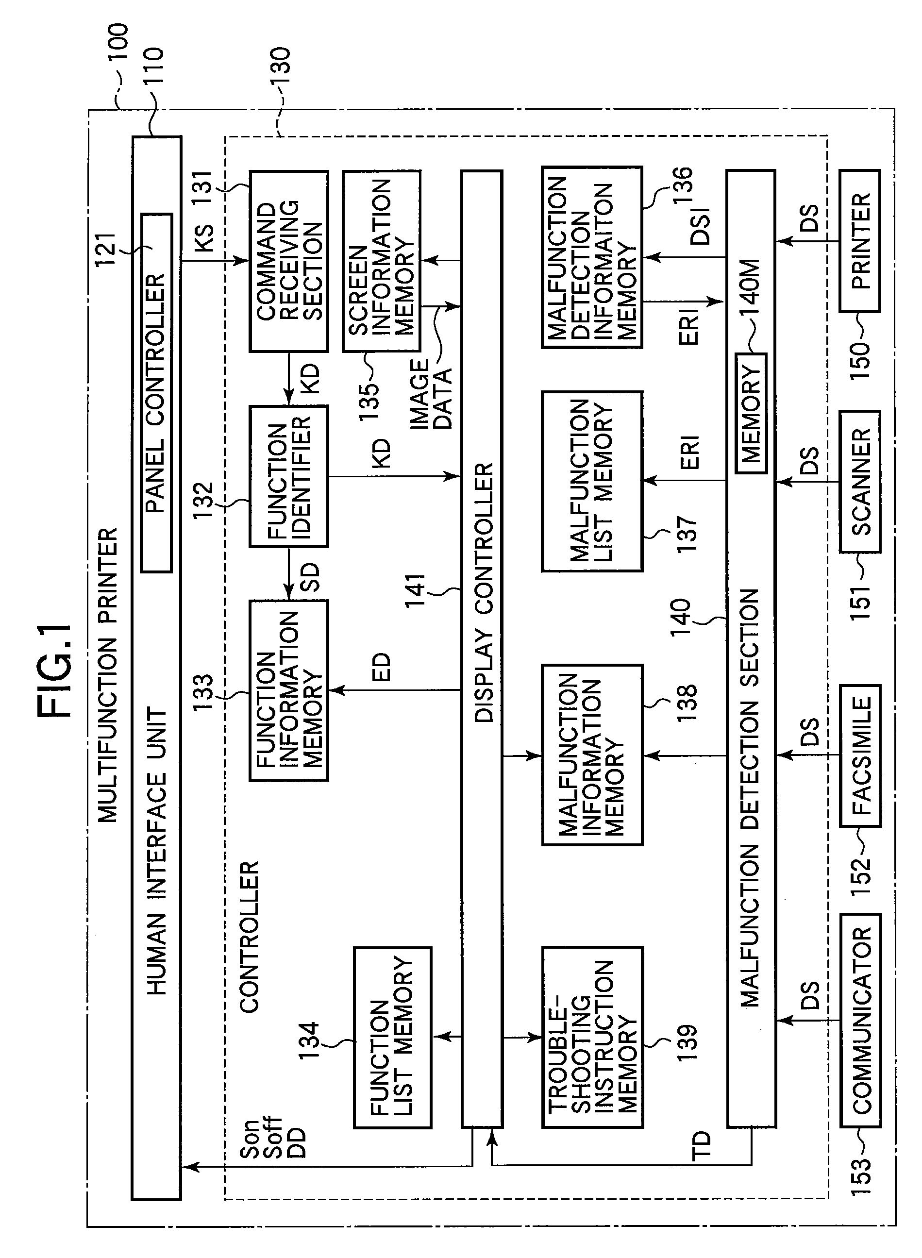
[0037]FIG. 1 is a block diagram illustrating a multifunction printer 100 according to a first embodiment of the invention. The multifunction printer 100 includes a human interface unit 110 and a controller 130. the multifunction printer 100 incorporates built-in devices including a printer 150, a scanner 151, a facsimile 152, and a communicator 153.

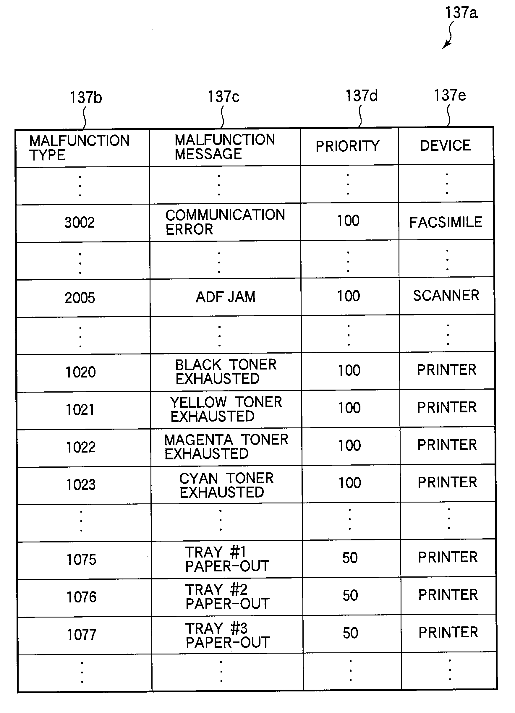
[0038]The controller 130 includes a command receiving section 131, a function identifier 132, a function information memory 133, a function list memory 134, a screen information memory 135, a malfunction detection information memory 136, a malfunction list memory 137, a malfunction information memory 138, a troubleshooting instruction memory 139, a malfunction detecting section 140, and a display controller 141.

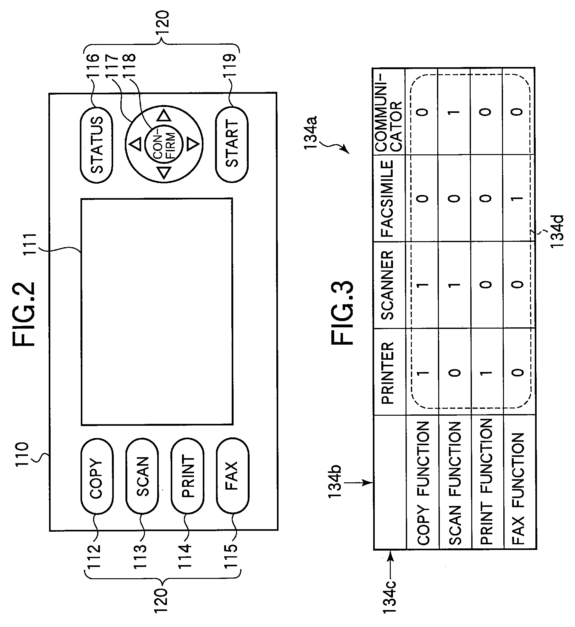
[0039]FIG. 2 illustrates the outline of the human interface unit 110. The human interface unit 110 includes a display unit 111 in the form of an LCD display, a command inputting section 120, and a panel control...

second embodiment

Overall Configuration

[0131]FIG. 14 is a block diagram illustrating the outline of a multifunction printer 200 according to a second embodiment. The multifunction printer 200 includes a human interface unit 110, a controller 230, a printer 150, a scanner 151, a facsimile 152, and a communicator 153. The multifunction printer 200 differs from the multifunction printer 100 in that the controller 230 is employed in place of the controller 130.

[0132]The controller 230 includes a command receiving section 131, a function identifier 132, a function information memory 133, a function list memory 134, a screen information memory 135, a malfunction detection information memory 136, a malfunction list memory 137, a malfunction information memory 138, a troubleshooting instruction memory 139, a malfunction detecting section 240, a display controller 241, a malfunction counter 242, and a malfunction count memory 243. The controller 230 is configured in a similar way to the controller 130. Howeve...


PUM


Abstract

A multifunction printer is capable of performing a plurality of functions. Each function is performed by a corresponding device incorporated in the multifunction printer. The multifunction printer includes a display unit, a malfunction detecting section, and a display controller. The malfunction detecting section is configured to detect a malfunction that has occurred within the multifunction printer. When one of the plurality of functions is selected, if the malfunction detecting section has detected the malfunction, the display controller causes the display unit to display a malfunction message indicative of the malfunction.

Description

BACKGROUND OF THE INVENTION[0001]1. Field of the Invention[0002]The present invention relates to a multifunction printer, and more particularly to a technique for displaying malfunctions of the multifunction printer to users.[0003]2. Description of the Related Art[0004]A multifunction printer performs, for example, the functions of printing, scanning, and faxing. A technique is known which displays on a display unit information indicative of a type of malfunction and a corresponding troubleshooting instruction if a multifunction printer fails. For example, Japanese Patent Application Publication No. 2007-331196 discloses a technique for displaying a list of troubleshooting instruction for remedying current malfunctions in response to a user's command.[0005]However, the technique disclosed in Japanese Patent Application Publication No. 2007-331196 suffers from the following problems. A plurality of troubleshooting instructions are displayed in list form for remedying a plurality of m...

Claims


Application Information

Patent Timeline
Patent Type & Authority Patents(United States)
IPC IPC(8): G06K15/00
CPCG03G15/55G06F11/0733G06F11/0781G03G15/502G06F11/327
Inventor URASAWA, KOJI
Owner OKI ELECTRIC IND CO LTD
Why Eureka
Try Eureka