Electric vehicle

a technology of electric motors and electric motors, applied in vehicle components, cycle control systems, cycle equipment, etc., can solve the problems of not immediately transmitting the power of electric motors to the wheels, user may fail to turn off walking-while-pushing switches,

Active Publication Date: 2019-09-10
YAMAHA MOTOR CO LTD
View PDF14 Cites 2 Cited by
  • Summary
  • Abstract
  • Description
  • Claims
  • Application Information

AI Technical Summary

Benefits of technology

[0019]According to this arrangement, an input to the human power input system is detected by the human power input detector, and it is judged based on its detection result whether the user is present in the vicinity of the vehicle body. Accordingly, a more reliable judgment becomes possible, and a driving force is appropriately generated based on a user's intention.
[0021]In a preferred embodiment of the present invention, the informer includes a display supported on the vehicle body. According to this arrangement, the drive-standby state is informed to the user via the display. Informing by the display is particularly effective when the user is present in the vicinity (for example, a range in which a display of the display unit is visible) of the vehicle body. When the user is away from the vicinity of the vehicle body, because the control state automatically transitions from the drive-standby state to the basic state, the necessity for informing is low in a situation where the user is away from the vicinity of the vehicle body. Therefore, informing by the display unit is appropriate and sufficient.

Problems solved by technology

However, if a user overlooks the indication by the indicator lamp or the like, the user may fail to turn off the walking-while-pushing switch.
Therefore, even when the operator is operated, the power of the electric motor is not immediately transmitted to the wheel.

Method used


Image

  • Electric vehicle
  • Electric vehicle
  • Electric vehicle

Examples


Embodiment Construction

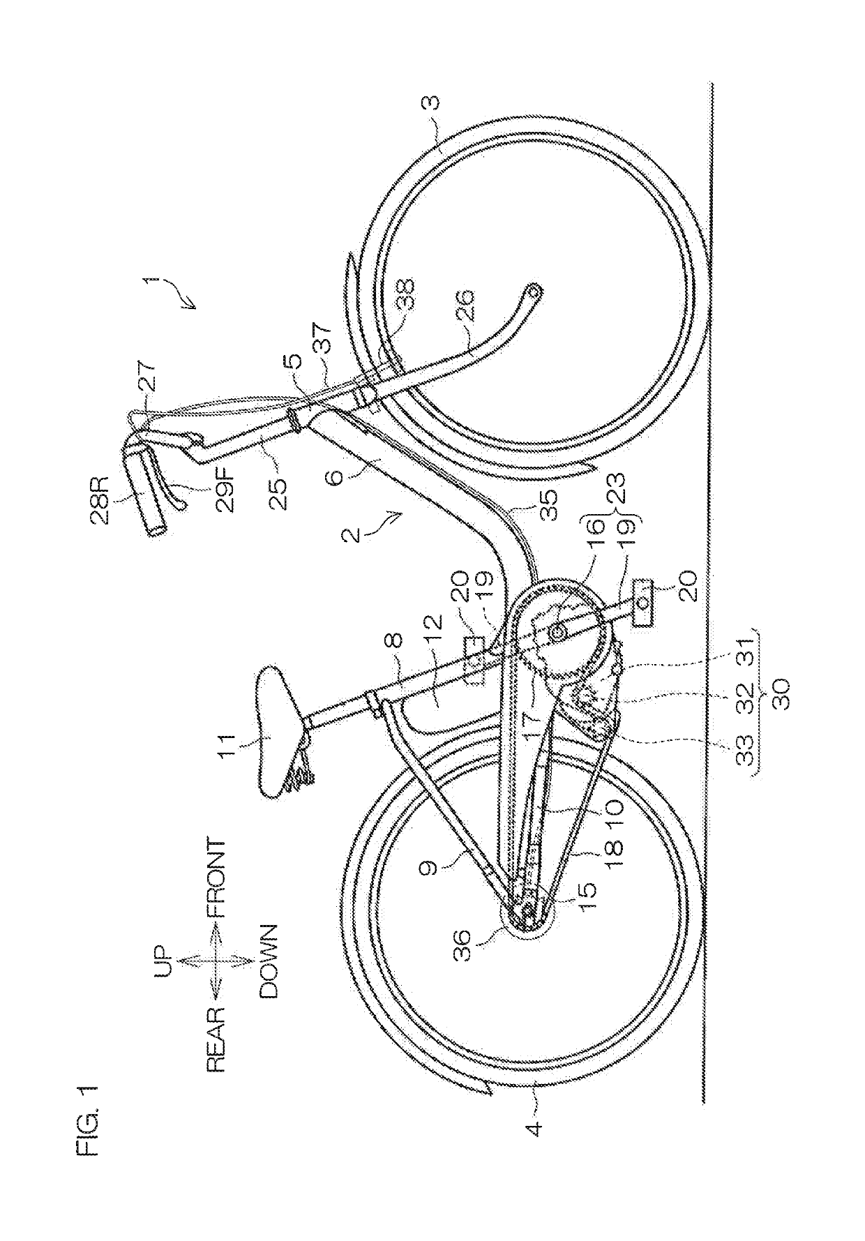
[0030]FIG. 1 is a side view for describing a configuration of a two-wheeled electric vehicle that is an example of an electric vehicle according to a preferred embodiment of the present invention. In the following description, the directions of front / rear and left / right refer to directions as viewed from a user seated on a saddle. That is, in FIG. 1, a right side surface of the two-wheeled electric vehicle 1 is presented.

[0031]The two-wheeled electric vehicle 1 is an electric vehicle provided with an arrangement to transmit a driving force from an electric motor to a wheel, and more specifically, is a saddle type electric vehicle. The two-wheeled electric vehicle 1 includes a front wheel 3 and a rear wheel 4. Further, the two-wheeled electric vehicle 1 includes a human power drive system to drive the rear wheel 4 by human power.

[0032]The two-wheeled electric vehicle 1 includes a vehicle body frame 2 that defines a vehicle body of a saddle type. The front wheel 3 and the rear wheel 4...


PUM


Abstract

An electric vehicle includes a vehicle body, an electric motor, a wheel, an operator operated by a user to drive the wheel to rotate by power from the electric motor, and a controller that controls the electric motor according to an operation of the operator. The controller includes a plurality of control states including a basic state, a drive-standby state which transitions to and from the basic state, and a driving state which transitions to and from the drive-standby state and causes transmission of power of the electric motor to the wheel. The controller is configured or programmed to transition to the driving state if the operator is operated in the drive-standby state and to transition to the basic state if it is judged in the drive-standby state that a user is not present in the vicinity of the vehicle body for a predetermined time or longer.

Description

BACKGROUND OF THE INVENTION[0001]1. Field of the Invention[0002]The present invention relates to an electric vehicle that transmits power from an electric motor to a wheel.[0003]2. Description of the Related Art[0004]Japanese Patent Application Publication No. 2000-095179 (JP 2000-095179A) discloses an electrically assisted bicycle. The electrically assisted bicycle includes a drive system driven by human power and a drive system driven by an electric motor. The electric motor assists the drive by human power and also assists driving of the vehicle during walking while pushing the same. A handle bar includes a walking-while-pushing switch attached thereto that is operated to be turned on and off. When a user turns on the walking-while-pushing switch and rotates a grip, the electric motor generates a walking-while-pushing assist force according to a rotation amount of the grip.SUMMARY OF THE INVENTION[0005]The inventor of preferred embodiments of the present invention described and c...

Claims


Application Information

Patent Timeline
Patent Type & Authority Patents(United States)
IPC IPC(8): B62M6/45B62M6/55B60K35/00B62K23/04
CPCB62M6/45B60K35/00B62M6/55B62K23/04B62K2204/00
Inventor OHASHI, TORUSARUWATARI, YUTAKAOZAWA, HIROKI
Owner YAMAHA MOTOR CO LTD
Why Eureka
Try Eureka