Hinged spinal fusion cages

a cage and spine technology, applied in the field of spine interbody devices, can solve the problems of undesired abnormal curvature of the spine, vertebrae may become compressed or otherwise damaged,

Active Publication Date: 2013-07-16
LIFE SPINE INC
View PDF28 Cites 123 Cited by
  • Summary
  • Abstract
  • Description
  • Claims
  • Application Information

AI Technical Summary

Benefits of technology

[0015]The various forms of the present interbody fusion cage include superior and inferior sides or bone abutment surfaces that have serrations, teeth or similar functioning structures (teeth). The teeth extend between the anterior end and the posterior end. The teeth may take different shapes but are configured to allow insertion of the spinal interbody fusion cage in an anterior-first manner while preventing and / or inhibiting the spinal interbody fusion cage from backing out posteriorly.

Problems solved by technology

With others, the vertebrae may become compressed or otherwise damaged.
In these and other cases the vertebrae can become too closely spaced anteriorly which causes an undesired abnormal curvature of the spine with respect to lordosis or kyphosis.

Method used


Image

  • Hinged spinal fusion cages
  • Hinged spinal fusion cages
  • Hinged spinal fusion cages

Examples


Embodiment Construction

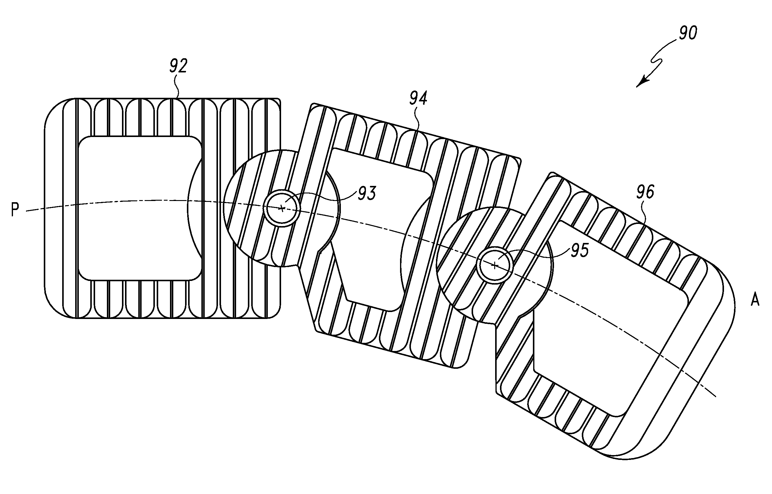
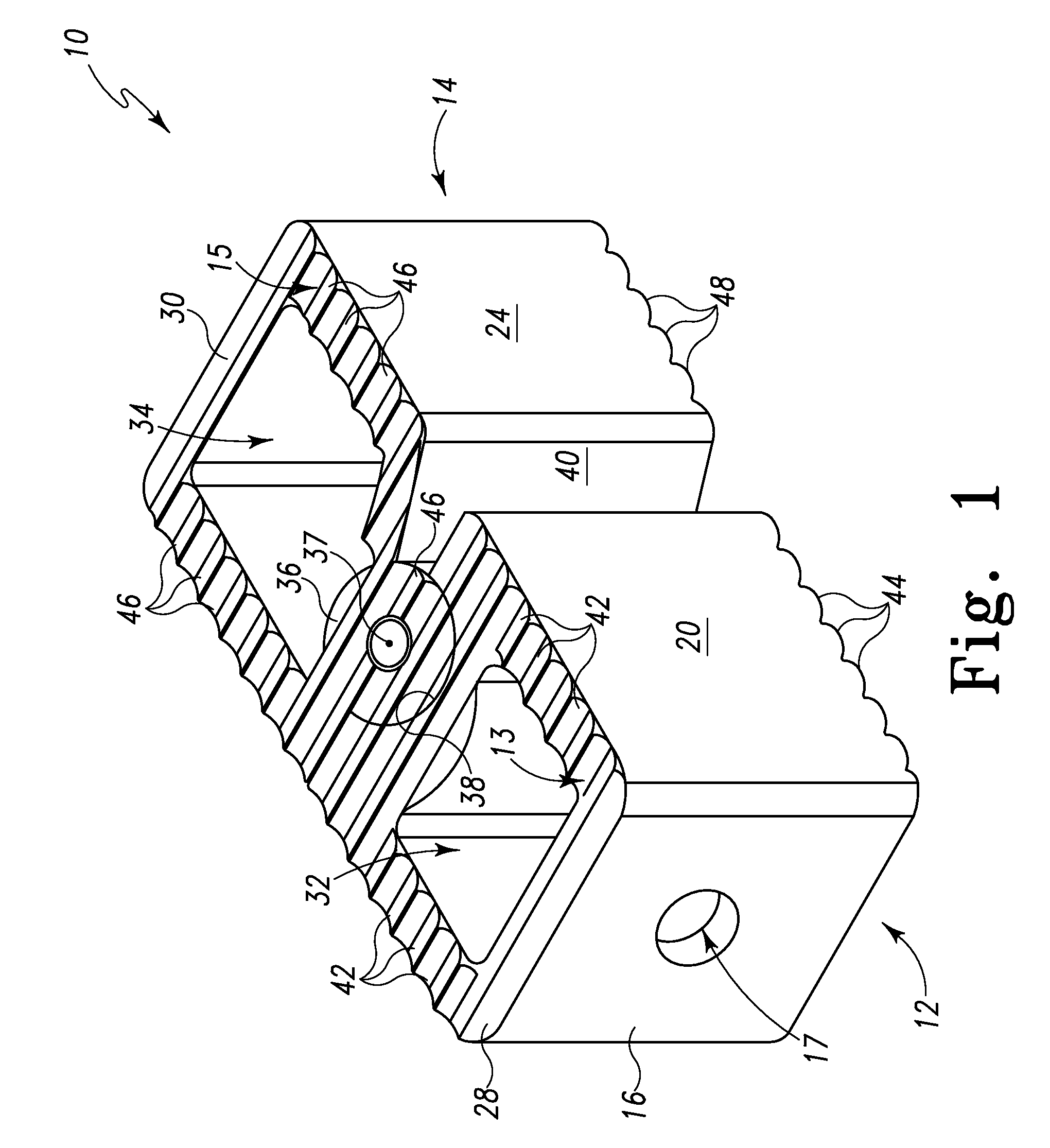
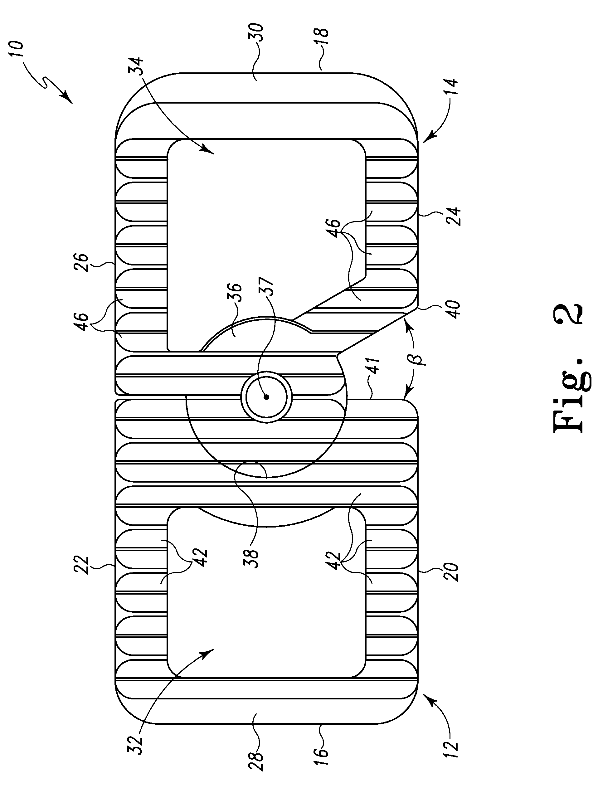
[0028]Referring to FIGS. 1-5, there is depicted an exemplary embodiment of a spinal interbody fusion cage or device, generally designated 10, fashioned in accordance with the present principles such that its 1) anterior to posterior (or posterior to anterior) profile and 2) lateral profile is changeable while its inferior to superior (or superior to inferior) height or profile remains constant. This is accomplished through angular positioning of a laterally pivoting portion of the body as described herein. The spinal interbody fusion cage 10 is utilized for implantation between a pair of adjacent vertebrae in order to provide distraction and support to the adjacent vertebrae and / or promote bone fusion between the adjacent vertebrae. The spinal interbody fusion cage 10 is sized to be received between the adjacent vertebrae and not extend beyond the periphery of the vertebrae. As such, the fusion cage 10 may be fabricated in various sizes to accommodate various sizes of lumbar vertebr...


PUM


Abstract

A spinal interbody fusion cage has a body whose anterior / posterior profile may be varied through angular positioning of one or more articulating segments of the body without changing the superior / inferior height of the body. The present spinal interbody fusion cage has N segments or sections wherein at least one segment is articulated relative to another segment via a connection point, pivot or pivot structure such that the anterior / posterior profile is variable through angular positioning of one or more of the segments. The pivot structure may be configured so as to allow unidirectional movement between the connecting segments thereby allowing articulation in one plane or to allow omni-directional movement between the connecting segments thereby allowing articulation in multiple planes. The various forms of the present interbody fusion cage include superior and inferior sides or bone abutment surfaces that have serrations, teeth or similar functioning structures (teeth). The teeth extend between the anterior end and the posterior end. The teeth may take different shapes but are configured to allow insertion of the spinal interbody fusion cage in an anterior-first manner while preventing and / or inhibiting the spinal interbody fusion cage from backing out posteriorly.

Description

RELATED APPLICATIONS[0001]This patent application claims the benefit of and / or priority to U.S. Provisional Patent Application Ser. No. 61 / 011,293 filed Jan. 16, 2008, entitled “Spinal Interbody Fusion Cages Providing Variable Anterior / Posterior Profiles” the entire contents of which is specifically incorporated herein by this reference.BACKGROUND OF THE INVENTION[0002]1. Field of the Invention[0003]The present invention relates to spinal interbody devices for implantation between a pair of adjacent vertebrae in order to provide distraction and support to the adjacent vertebrae and / or promote bone fusion between the adjacent vertebrae.[0004]2. Background Information[0005]The disc between vertebrae of a human spine is sometimes damaged due to disease or injury, or may simply deteriorate due to age, disease, injury or congenital defect. With others, the vertebrae may become compressed or otherwise damaged. In these and other cases the vertebrae can become too closely spaced anteriorly...

Claims


Application Information

Patent Timeline
Patent Type & Authority Patents(United States)
IPC IPC(8): A61F2/44
CPCA61F2/447A61F2002/30471A61F2002/30538A61F2002/30904A61F2002/4475A61F2002/448A61F2220/0091A61F2250/0006A61F2310/00017A61F2310/00023A61F2002/30593
Inventor BUTLER, MICHAEL S.HARTSELL, BRIAN D.
Owner LIFE SPINE INC
Why Eureka
Try Eureka