
Anti-slip assembly for a staple gun

a staple gun and anti-slip technology, which is applied in the field of anti-slip assembly, can solve the problems of not being able to provide a preferred quality of construction to the conventional staple gun, the accuracy of the firing pin, and the inability to accurately impact the staples, so as to achieve convenient operation and preferred construction quality

Active Publication Date: 2013-07-23
TESTO IND
View PDF4 Cites 0 Cited by
  • Summary
  • Abstract
  • Description
  • Claims
  • Application Information

AI Technical Summary

Benefits of technology

[0007]The main objective of the present invention is to provide an anti-slip assembly for a staple gun that can hold the staples of the staple gun securely when the staple gun is used, can operate conveniently and can provide a preferred quality of construction to the staple gun.

Problems solved by technology

Although an elastic panel mounted in the staple magazine can push the staples to upwardly return to the original position, the moved staples may misalign with the firing pin and the firing pin cannot impact the staples accurately to eject and cannot provide a preferred quality of construction to the conventional staple gun.

Method used


Image

  • Anti-slip assembly for a staple gun
  • Anti-slip assembly for a staple gun
  • Anti-slip assembly for a staple gun

Examples


Embodiment Construction

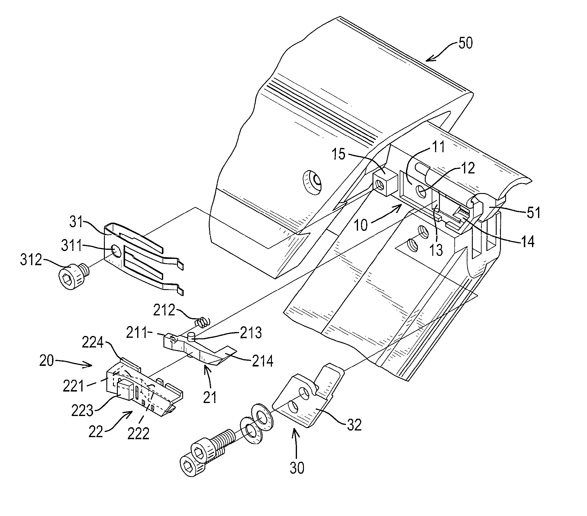
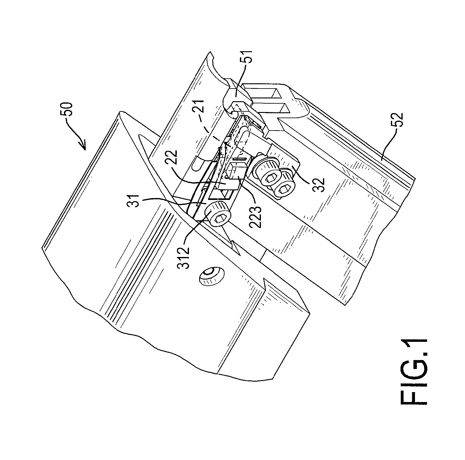
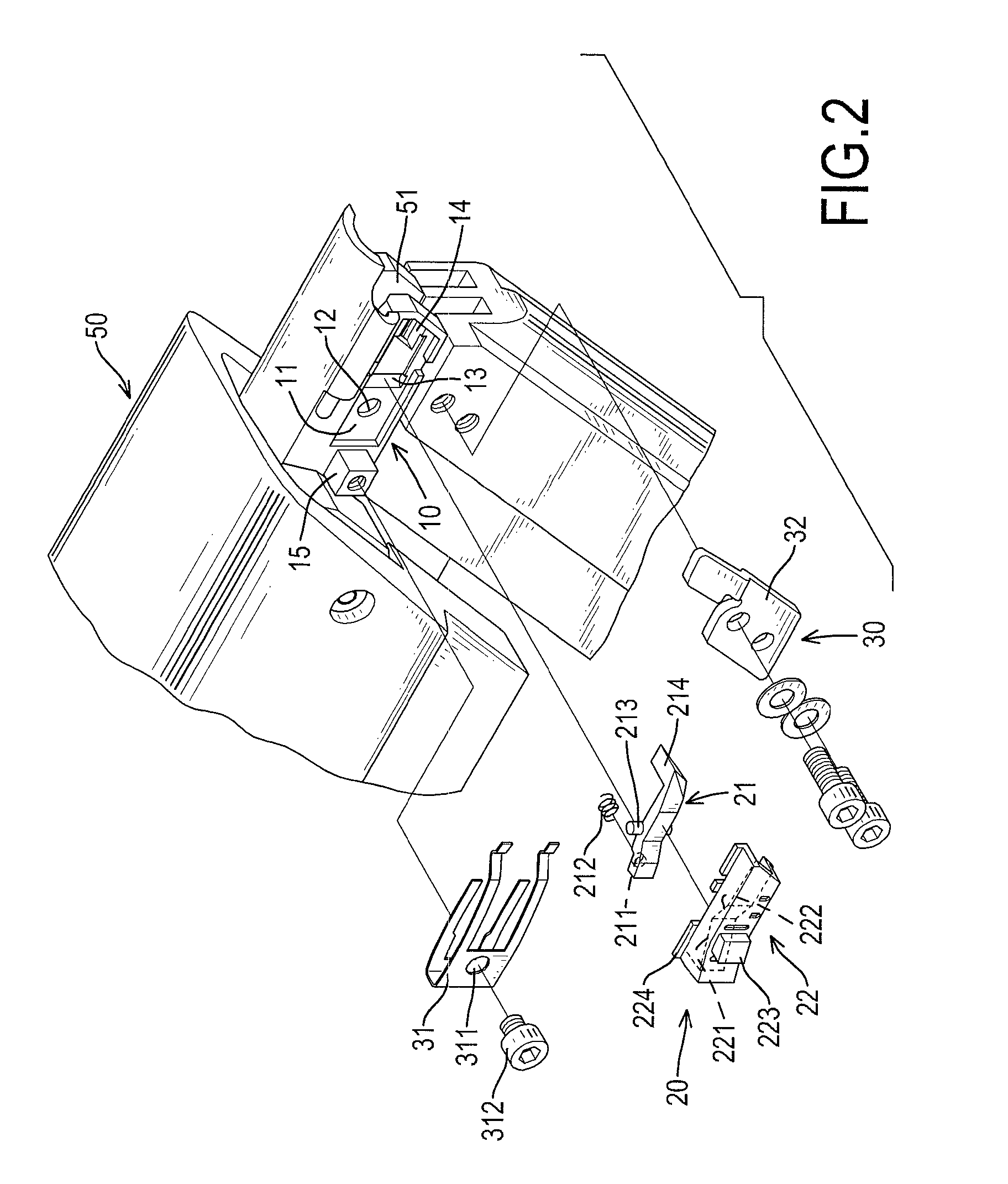
[0015]With reference to FIGS. 1 and 2, an anti-slip assembly in accordance with the present invention is mounted on a staple gun 50 and comprises a mounting device 10, an operating device 20 and a limiting device 30.

[0016]With further reference to FIG. 3, the staple gun 50 has a gun shaped body and a staple magazine 52. The gun shaped body has a front end, a bottom end, a sidewall and a muzzle 51. The muzzle 51 is formed in the front end of the gun shaped body of the staple gun 50. The staple magazine 52 is obliquely connected to the top end and the bottom end of the body and has a chamber and a pushing frame 53. The chamber is formed in the staple magazine 52, communicates with the muzzle 51 of the body and stores a staple row 60 inside. The pushing frame 53 is slidably mounted in the chamber of the staple magazine 52 to push the staples 61 of the staple row 60 moving upwardly to the muzzle 51 of the body of the staple gun.

[0017]The mounting device 10 is formed in the sidewall of t...


PUM


Abstract

An anti-slip assembly for a staple gun has a mounting device, an operating device and a limiting device. The mounting device is formed in the staple gun and has a mounting recess, a positioning recess, a pivotal recess and a through hole. The operating device is movably connected to the mounting device and has an anti-slip arm and an operating cap. The anti-slip arm is rotatably mounted in the mounting recess and has a mounting rod, a spring, a pivotal rod and an abutting stem. The operating cap is movably mounted in the mounting recess, is mounted around the anti-slip arm and has a releasing recess, a pressing recess, a pushing protrusion and at least one holding flange. The limiting device is detachably connected to mounting device and the staple gun and has a limiting frame and a limiting panel.

Description

BACKGROUND OF THE INVENTION[0001]1. Field of the Invention[0002]The present invention relates to an anti-slip assembly, and more particularly relates to an anti-slip assembly for a staple gun that can hold the staples of the staple gun securely when the staple gun is in use, can operate conveniently and can provide a preferred quality of construction to the staple gun.[0003]2. Description of Related Art[0004]Conventional staple guns are used extensively with decorations, shoemaking and leatherwear and shoot staples into objects. A conventional staple gun has a firing pin mounted in a body of the conventional staple gun to impact the staple mounted in a staple magazine of the conventional staple gun to eject out of a muzzle of the conventional staple gun.[0005]However, the firing pin of the conventional staple gun can be moved fleetly and continuously to impact the staples to eject out of the conventional staple gun, the staples mounted below the ejecting staple may be moved downward...

Claims


Application Information

Patent Timeline
Patent Type & Authority Patents(United States)
IPC IPC(8): B25C7/00B25C5/00
CPCB25C5/1637
Inventor LIAO, MIN-HO
Owner TESTO IND
Learn More