Injection device comprising several coupling mechanisms

a coupling mechanism and injection device technology, applied in the field of devices, can solve the problems of requiring a relatively complicated structure, and achieve the effects of avoiding frictional losses during the rotation of the rotatable element, simple development, and avoiding frictional losses during the administration

Active Publication Date: 2013-07-23
YPSOMED AG
View PDF45 Cites 46 Cited by
  • Summary
  • Abstract
  • Description
  • Claims
  • Application Information

AI Technical Summary

Benefits of technology

[0033]In some preferred embodiments, the detent element is constructed integrally with the spring element. This leads to a simple development. The detent element can be constructed as a projection, protruding in the direction of the rotation axis, on the spring element. This is advantageous when the spring element, as described above, has the form of a curved ring.
[0034]In some embodiments, the injection device can further have at least one ball bearing which absorbs forces which are transmitted between the delivery element and the housing. By a ball bearing being provided, frictional losses caused during the administering owing to the transmission of forces between the delivery element and the housing, are largely minimized.
[0035]In some preferred embodiments, the ball bearing is advantageously arranged such that it absorbs (axial) forces acting along the thrust axis, which are transmitted from the delivery element (locked with respect to rotation relative to the housing) via the rotatable element to the housing, i.e. which act between the rotatable element and the housing. Expressed in general terms, axial forces, e.g. acting in proximal direction, are therefore transmitted between the delivery element and the housing via a rotatable connection which is secure with respect to displacement in axial direction. For this, in the prior art, generally a sliding connection is provided between the rotatable element and the housing or an element which is fixed to the housing. In the present embodiment, on the other hand, at least one ball bearing is provided, which is arranged between the rotatable element or an element connected therewith on the one hand, and the housing or an element which is fixed to the housing at least during the administering, on the other hand. Thereby, frictional losses during the rotation of the rotatable element can be avoided.
[0036]In some preferred embodiments, two ball bearings are present, which are arranged so that they can absorb forces along the thrust axis both in a proximal (rearward) direction and also in the opposite, distal (forward) direction, i.e. the direction in which the thrust takes place. Axial forces in the proximal direction occur generally during the administering, whereas axial forces in the distal direction can occur when the delivery element is spring-loaded in the distal direction, as may be the case in some preferred embodiments. The spring serving for this is sufficiently weak that it does not cause any ejection of the product out of the reservoir. Rather, it serves, in a change of reservoir, to automatically bring the delivery element into its distal final position, i.e. to extend it completely, when the reservoir is removed from the housing. When the delivery element is in a suitable connection with the rotatable element, this leads to the rotatable element being set into a rotation when the delivery element moves out due to the spring force. To keep the spring force, which is necessary for this, small, a ball bearing is advantageous, because with the extending of the delivery element, it minimizes the frictional forces acting then.

Problems solved by technology

A disadvantage in the preceding arrangement is that when the triggering element is not pressed in completely, only the connection between the triggering element and the drive arrangement is released, without, however, an administering being triggered.
Accordingly, this requires a relatively complicated structure.

Method used


Image

  • Injection device comprising several coupling mechanisms
  • Injection device comprising several coupling mechanisms
  • Injection device comprising several coupling mechanisms

Examples


second embodiment

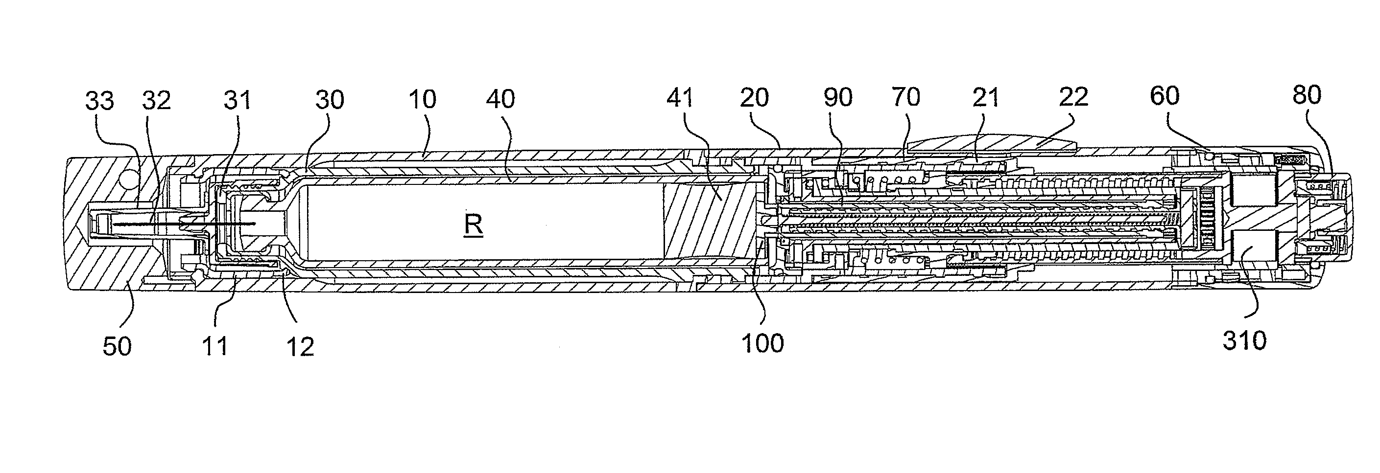
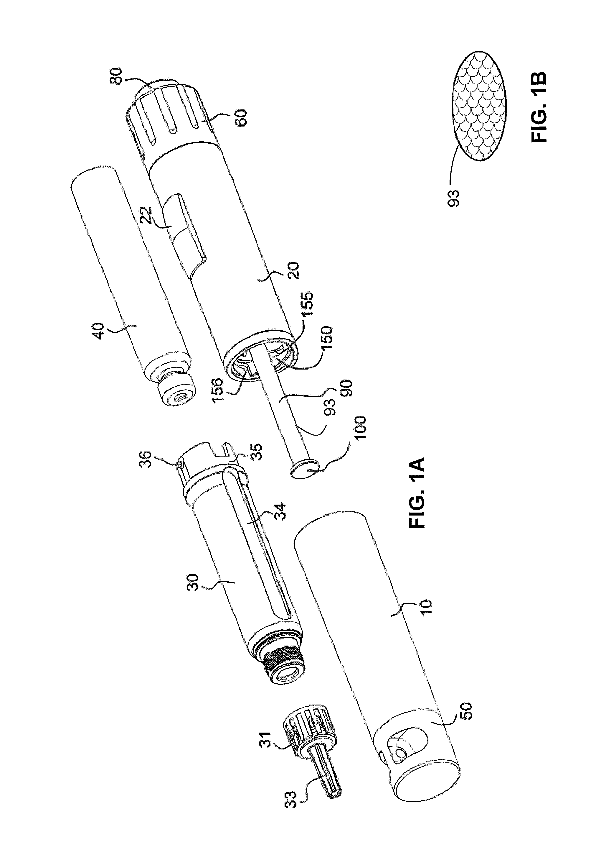
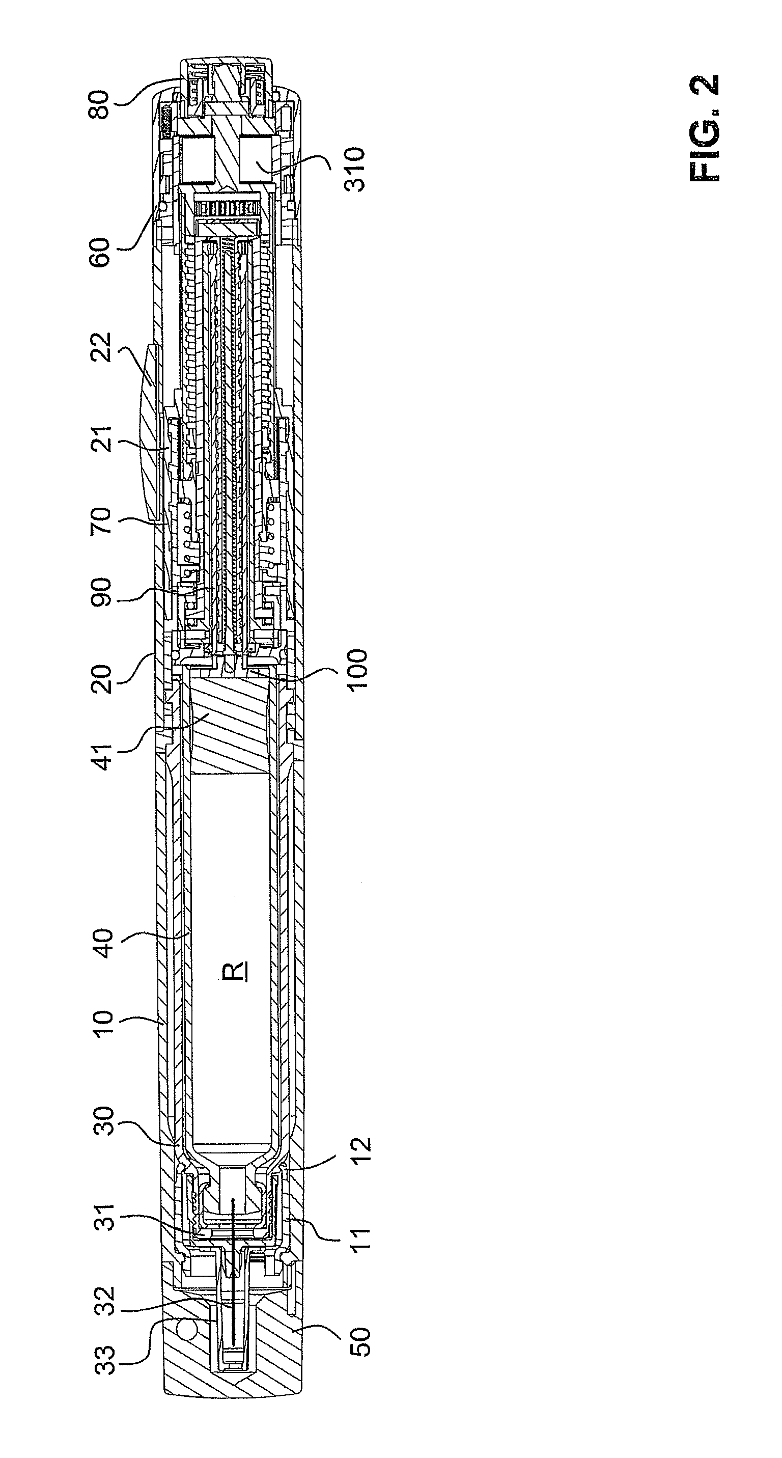
[0140]In the second embodiment, the stop sleeve 240 is omitted. Rather, its function is taken over by the correspondingly extended housing sleeve 20.

[0141]The drive arrangement which, in the first embodiment, apart from the spiral spring 310, is formed from the coupling disc 270, coupling shaft 230 and transmission sleeve 210, is formed in the second embodiment by different parts, including a connecting shaft 400 (with coupling disc 401 formed integrally thereon), a first transmission sleeve 410 closed at the proximal end, and a second transmission sleeve 420 adjoining distally thereto. These three parts are, in turn, connected rigidly with each other.

[0142]Whereas in the first embodiment, the display drum served to indicate the set dose and to delimit the maximum individual dose which was able to be set in the dosing direction and to delimit the movement in the distribution direction, the latter function in the second embodiment is taken over by a second dose limiting ring 430. The...

first embodiment

[0144]Apart from these differences, the structure and mode of operation of the injection device are substantially the same as in the

[0145]The differences between the first and the second embodiment show that the functions of an injection device according to the present invention can be reached in a variety of ways and the invention is in no way restricted to the exemplary embodiments. Various further modifications are possible, which may be due to manufacturing requirements.


PUM


Abstract

An injection device including a drive unit, a delivery unit, a dosing unit, a trigger for triggering an injection, a first coupling mechanism between the drive unit and the delivery unit, and a second coupling mechanism between the dosing unit and the drive unit, wherein the drive unit is tensioned by a rotation of the dosing unit and when the drive unit is tensioned the first coupling mechanism is disengaged and the second coupling mechanism is engaged, and wherein when an injection is triggered first the first coupling mechanism is engaged and then the second coupling mechanism is disengaged. In some embodiments, the device may include a third coupling mechanism which only releases the delivery unit after the engagement and disengagement which follow a triggering.

Description

CROSS-REFERENCED RELATED APPLICATIONS[0001]This application is a continuation of U.S. patent application Ser. No. 12 / 403,887, filed on Mar. 13, 2009, issued as U.S. Pat. No. 8,048,037 on Nov. 1, 2011, which is a continuation of International Patent Application PCT / CH2007 / 000243 filed May 11, 2007, which claims priority to Swiss Patent Application 1475 / 06 filed Sep. 15, 2006, the entire contents of all of which are incorporated herein by reference.BACKGROUND[0002]The present invention relates to devices for administering, injecting, delivering, infusing or dispensing a substance, and to methods of making and using such devices. More particularly, it relates to such a device for delivering a fluid product, wherein the device can be developed as an injection device for the injection of an adjustable dose of the product and can take the form of an injection pen, i.e. a compact injection device in pen-like form.[0003]A large number of injection devices are known from the prior art for th...

Claims


Application Information

Patent Timeline
Patent Type & Authority Patents(United States)
IPC IPC(8): A61M5/315A61M5/00
CPCA61M5/20A61M5/31583A61M5/31553A61M5/31513A61M5/31585A61M5/31535A61M5/31541A61M5/31561A61M5/31563A61M5/31568A61M5/31593A61M2205/581A61M2005/202A61M5/31543A61M2202/04A61M5/24A61M2005/3154
Inventor KOHLBRENNER, PHILIPPESTETTLER, PETERHOSTETTLER, PATRICKWITTMANN, JUERGENWITTWER, MARTIN
Owner YPSOMED AG
Why Eureka
Try Eureka