Multi-stage switch system

a switch system and multi-stage technology, applied in the field of communication technologies, can solve the problems of system cost increase and system switching performance degradation, and achieve the effect of reducing the bandwidth occupancy of the

Active Publication Date: 2013-07-23
HUAWEI TECH CO LTD
View PDF10 Cites 27 Cited by
  • Summary
  • Abstract
  • Description
  • Claims
  • Application Information

AI Technical Summary

Benefits of technology

[0008]Embodiments of the present invention provide a multi-stage switch system to timely respond to the flow control information sent from a downstream switch unit to an upstream switch unit in a multi-stage switch fabric.
[0010]The multi-stage switch system provided in embodiments of the present invention can forward packets within the chassis by means of buffering the packets when guaranteeing the three-stage packet forwarding, and thus reducing the bandwidth occupancy of the FCC.

Problems solved by technology

Thus, sufficient interconnection bandwidth is required between the LCC and the FCC in order to meet the performance requirement and the system costs are increased.
In addition, the switching performance of the system may be degraded because the traffic flowing to the S2 increases.

Method used


Image

  • Multi-stage switch system
  • Multi-stage switch system
  • Multi-stage switch system

Examples


embodiment 1

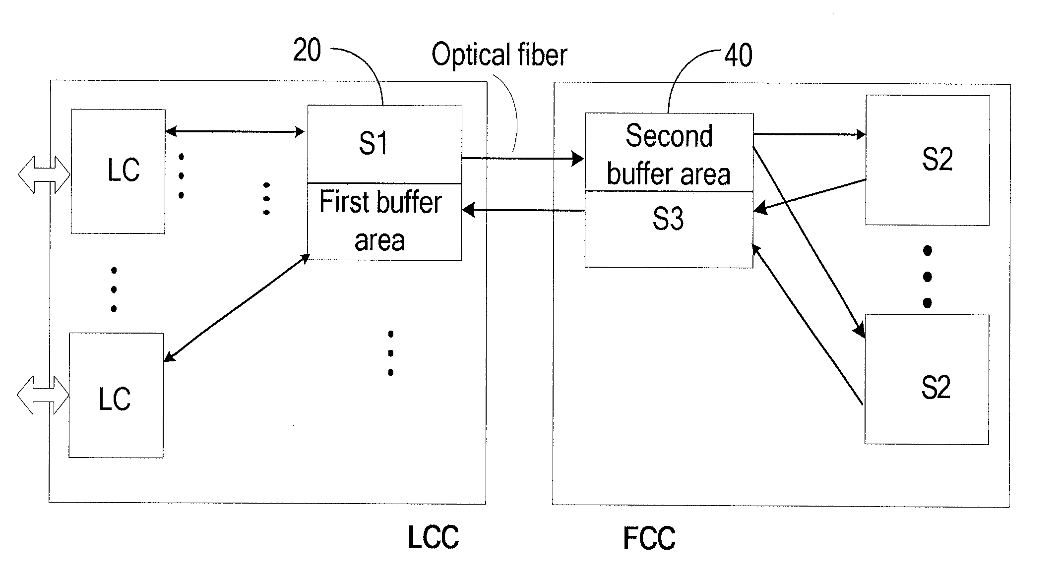
[0024]As shown in FIG. 6, a system is provided in Embodiment 1 of the present invention. The system includes at least one FCC, and one or more LCCs.

[0025]The FCC includes an S1, an S2, and an S3, where the S3 corresponds to the S1, and the S2 is connected to the S1 and S3 separately.

[0026]The LCC includes an interface component and an LC connected to the interface component, where the interface component is connected to the S1 and S3 in the FCC separately.

[0027]The interface component may be an S0 or an RPT. If the interface component is an S0, packets may be switched within the same LCC.

[0028]The FCC in the SF provided in Embodiment 1 includes: an S1, an S2, and an S3, where the S3 corresponds to the S1, and the S2 is connected to the S1 and S3 separately. The S1, S2, and S3 are located in the FCC. Therefore, when a switch element generates flow control information and requires another switch element or an LC to respond to the flow control information, a timely response can be rece...

embodiment 2

[0029]As shown in FIG. 7, a multi-stage switch system is provided in Embodiment 2 of the present invention. The multi-stage system includes at least one FCC, and one or more LCCs.

[0030]The LCC includes an LC and an RPT.

[0031]The FCC includes: an S1, an S2, and an S3, where the S3 corresponds to the S1, the S2 is connected to the S1 and S3 separately, and the S1 and S3 can be connected to the S2 through an electrical backplane or an optical fiber in the FCC.

[0032]Through this SF, the packets may be switched between different LCs. The packet format is shown in Table 1.

[0033]

TABLE 1Destination LCC IDDestination LC IDFragment#PayloadFragment# indicates that the packet is a fragment of a large packet.

[0034]Specifically, the process of packet switching between different LCs includes: The RPT receives a packet sent by the source LC, and sends the packet to the S1 in the FCC through an optical fiber; according to a certain algorithm such as a load balancing algorithm, the S1 selects an S2, ...

embodiment 3

[0040]As shown in FIG. 8, a multi-stage switch system is provided in Embodiment 3 of the present invention. The multi-stage switch system includes at least one FCC, and one or more LCCs.

[0041]The LCC includes an LC and an S0. The FCC includes: an S1, an S2, and an S3, where the S3 corresponds to the S1, the S2 is connected to the S1 and S3 separately, and the S1 and S3 can be connected to the S2 through an electrical backplane or an optical fiber in the FCC. FIG. 8 shows a one-to-one mapping relationship between the S0 and the S1 / 3 (“S1 / 3” indicates that the S1 corresponds to the S3). In fact, a many-to-many mapping relationship exists between the S0 and the S1 / 3. In the following description, the mapping relationship is a one-to-one relationship.

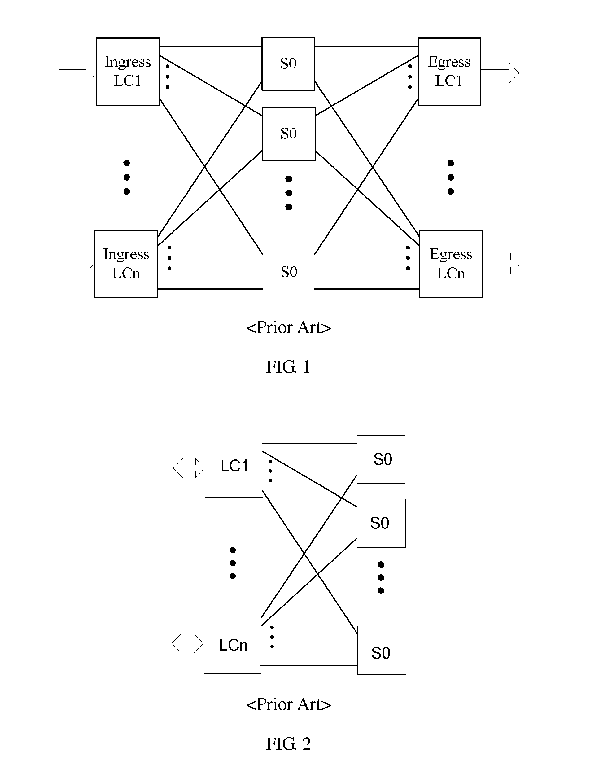
[0042]To make the embodiments of the present invention clearer, the following describes a single-stage SF briefly. In a single-stage SF, the LC and S0 are located in an LCC, and can be interconnected through an electrical backplane or an op...


PUM


Abstract

A multi-stage switch system includes a line card chassis (LCC) and a fabric card chassis (FCC). The LCC is configured with multiple line cards (LCs) and the FCC is configured with a stage-2 switch element (S2). The multi-stage switch system further includes a first switch combination and a second switch combination. The first switch combination and the second switch combination are configured on the LCC and the FCC respectively, and multiple LCs establish cross communication through the first switch combination, the second switch combination, and the S2. The first switch combination includes a stage-1 switch element (S1) and a first buffer area and the second switch combination includes a stage-3 switch element (S3) and a second buffer area. The multi-stage switch system can forward packets within the chassis by means of buffering the packets when guaranteeing the three-stage packet forwarding, and thus reducing the bandwidth occupancy of the FCC.

Description

CROSS REFERENCE TO RELATED APPLICATION[0001]This application claims priority to Chinese Patent Application No. 200910109298.9, filed on Aug. 12, 2009, which is hereby incorporated by reference in its entirety.FIELD OF THE INVENTION[0002]The present invention relates to communication technologies, and in particular, to a multi-stage switch system.BACKGROUND OF THE INVENTION[0003]A switch fabric (SF) may include one or more stages of switch elements, as shown in FIG. 1, FIG. 2, FIG. 3, and FIG. 4. The SF shown in FIG. 1 and FIG. 2 includes a stage-0 switch element (S0) and multiple line cards (LCs). The SF shown in FIG. 3 and FIG. 4 includes three stages of switch elements and multiple LCs. In FIG. 1 and FIG. 3, the LC that sends uplink data flows (ingress LC) is located on one side of the switch element, and the LC that receives downlink data flows (egress LC) is located on the other side of the switch element. The LC in FIG. 2 and FIG. 4 can send uplink data flows and can also recei...

Claims


Application Information

Patent Timeline
Patent Type & Authority Patents(United States)
IPC IPC(8): H04J3/14
CPCH04L49/1515H04L49/3018H04L49/3027H04L49/3072H04L49/45
Inventor LIN, YUN
Owner HUAWEI TECH CO LTD
Why Eureka
Try Eureka