Utility vehicle

a technology for utility vehicles and seat supports, applied in the field of utility vehicles, can solve the problems of increased cost of seat supports, difficulty in efficient maintenance operation by operators, and easy access to engines, and achieve the effect of mounting to the main frame easily and efficiently, and maintaining easily and efficiently

Active Publication Date: 2013-08-06
KAWASAKI MOTORS LTD
View PDF8 Cites 15 Cited by
  • Summary
  • Abstract
  • Description
  • Claims
  • Application Information

AI Technical Summary

Benefits of technology

[0007]In such a configuration, the sub-frame can be detached from the main frame by separating the both end portions of the first cross member from the second pillar pipe elements. By detaching the sub-frame from the main frame, a space can be provided in the vicinity of the engine mounted on the main frame. Therefore, the engine can be mounted to the main frame easily and efficiently, and the engine can be maintained easily and efficiently. In addition, the main frame can be reinforced by the sub-frame.

Problems solved by technology

In this construction, when an operator carries out maintenance of the engine, the operator cannot easily access the engine, which makes it difficult for the operator to carry out a maintenance operation efficiently.
In this technique, however, because of a complex structure of the seat support frame, a cost of the seat support frame increases.

Method used


Image

  • Utility vehicle
  • Utility vehicle
  • Utility vehicle

Examples


embodiment 1

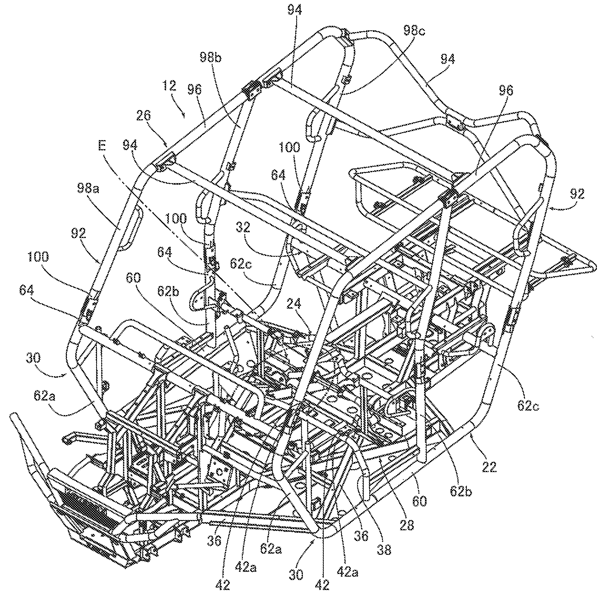
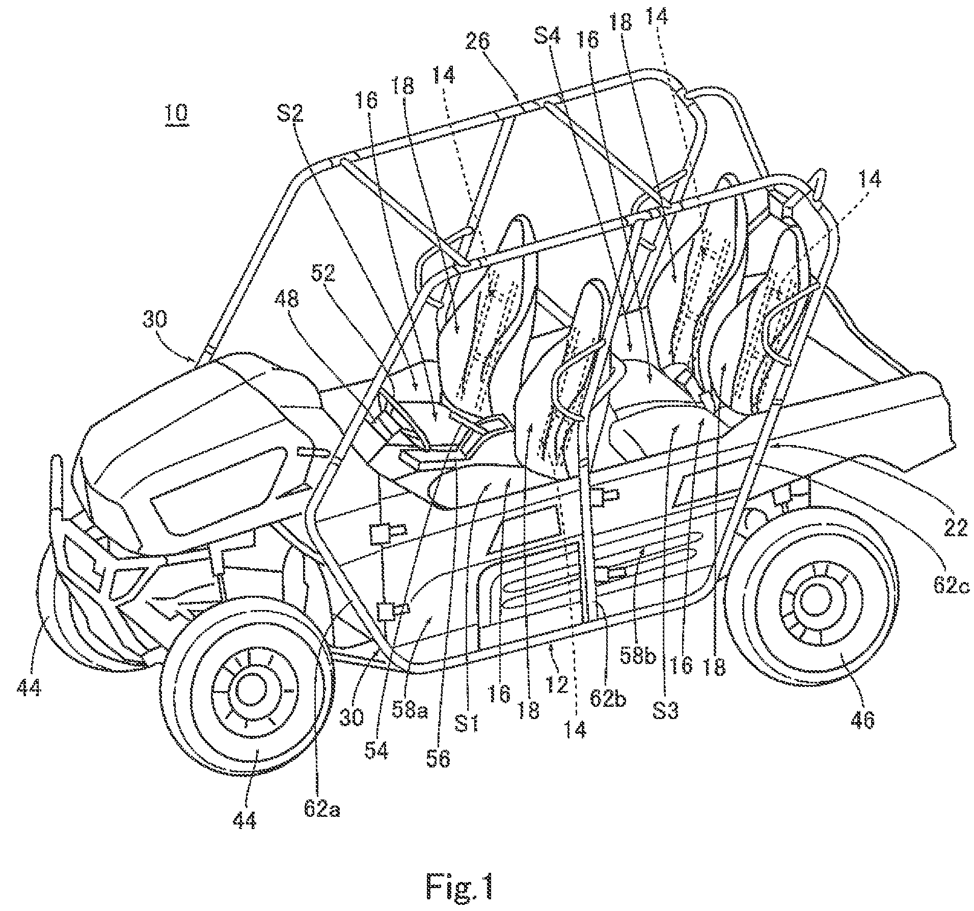
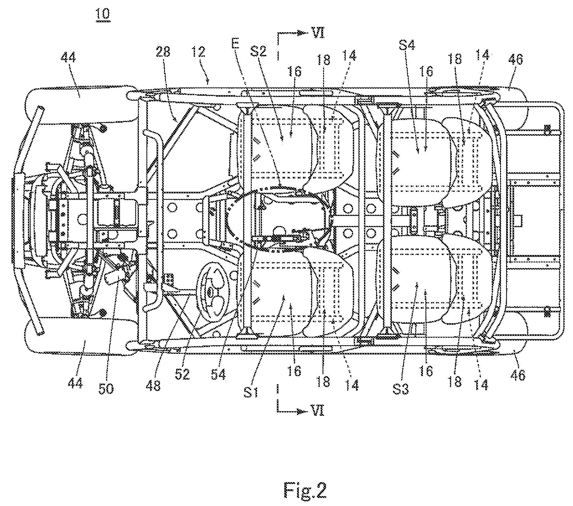
[0030]FIG. 1 is a perspective view showing an external appearance of a utility vehicle 10 according to FIG. 2 is a plan view showing a configuration of the utility vehicle 10. FIG. 3 is a perspective view showing a state where a seat S1 is mounted to a vehicle body frame 12, as viewed from obliquely downward.

[0031]Referring to FIGS. 1 to 3, the utility vehicle 10 includes the vehicle body frame 12, four seat frames 14 mounted to the vehicle body frame 12, seat bottoms 16 mounted to the four seat frames 14, respectively, and seat backrests 18 mounted to the four seat frames 14, respectively. Each of the four independent seats S1 to S4 includes the seat frame 14, the seat bottom 16 and the seat backrest 18. In this embodiment, the seats S1 and S2 at the front side are arranged side by side in a rightward and leftward direction, and the seats S3 and S4 are arranged side by side in the rightward and leftward direction, behind the seats S1 and S2, respectively. The seat S1, located at t...

embodiment 3

[0069]FIG. 19 is a perspective view showing a configuration of a joint member 206 of the sub-frame 24 according to As shown in FIG. 19, the joint member 206 has a substantially cylindrical shape formed by joining a first portion 208a and a second portion 208b to each other. The first portion 208a has a first contact portion 210a of a substantially semi-cylindrical shape, which contacts an outer surface of the first portion 202 and an outer surface of the second portion 204. A first engagement portion 212a is formed at one end portion of the first contact portion 210a in a circumferential direction, while a first fastening portion 216a having two holes 214a is formed at an opposite end portion of the first contact portion 210a in the circumferential direction, to extend radially. The second portion 208b has a second contact portion 210b of a substantially semi-cylindrical shape, which contacts the outer surface of the first portion 202 and the outer surface of the second portion 204...


PUM


Abstract

A utility vehicle comprises a vehicle body frame including a main frame including a floor member and a pair of right and left side members and a sub-frame for reinforcing the main frame, each of the side members includes a side pipe element, a first pillar pipe element, a second pillar pipe element and a third pillar pipe element, the sub-frame includes a first cross member provided between and coupled to second pillar pipe elements, one end portion of the first cross member is detachably coupled to one of the second pillar pipe elements and an opposite end portion of the first cross member is detachably attached to the other second pillar pipe element.

Description

BACKGROUND OF THE INVENTION[0001]1. Field of the Invention[0002]The present invention relates to a utility vehicle including a vehicle body frame including a main frame and a sub-frame for reinforcing the main frame.[0003]2. Description of the Related Art[0004]Typically, in utility vehicles, an engine is mounted to a center portion of a vehicle body frame, and pipe members constituting the vehicle body frame are arranged to cover the engine. In this construction, when an operator carries out maintenance of the engine, the operator cannot easily access the engine, which makes it difficult for the operator to carry out a maintenance operation efficiently.[0005]Under the circumstances, techniques for enabling the operator to easily access the engine have been developed. One example of these techniques is disclosed in Japanese Laid-Open Patent Application Publication No. 2007-276703. In the prior art disclosed in this publication, since a seat support frame of a vehicle body frame, whic...

Claims


Application Information

Patent Timeline
Patent Type & Authority Patents(United States)
IPC IPC(8): B60K5/00B62D21/00B60K5/10
CPCB60N2/012B60N2/643B60N2/682B60N2/686B62D21/183B62D23/005B62D39/00B60K5/02B60K2005/003
Inventor TSUMIYAMA, YOSHINORIKAKU, HIDETOSHIFURMAN, TYLERMAEDA, KAZUHIRO
Owner KAWASAKI MOTORS LTD
Why Eureka
Try Eureka