Combined high-voltage switch cabinet

A high-voltage switchgear, combined technology, applied in the direction of pull-out switchgear, switchgear, electrical components, etc., can solve the problem of time-consuming and laborious, save space, solve the waste of space and cost, and reduce installation and use. cost effect

Pending Publication Date: 2018-06-08
魏怡琪
View PDF0 Cites 1 Cited by
  • Summary
  • Abstract
  • Description
  • Claims
  • Application Information

AI Technical Summary

Problems solved by technology

The switchgear needs to be stabilized and maintained in a horizontal state during the transportation process. There is no special handling device for the switchgear in the prior art, and most of them are manually carried to the ordinary trolley,

Method used


Image

  • Combined high-voltage switch cabinet
  • Combined high-voltage switch cabinet
  • Combined high-voltage switch cabinet

Examples


Embodiment 1

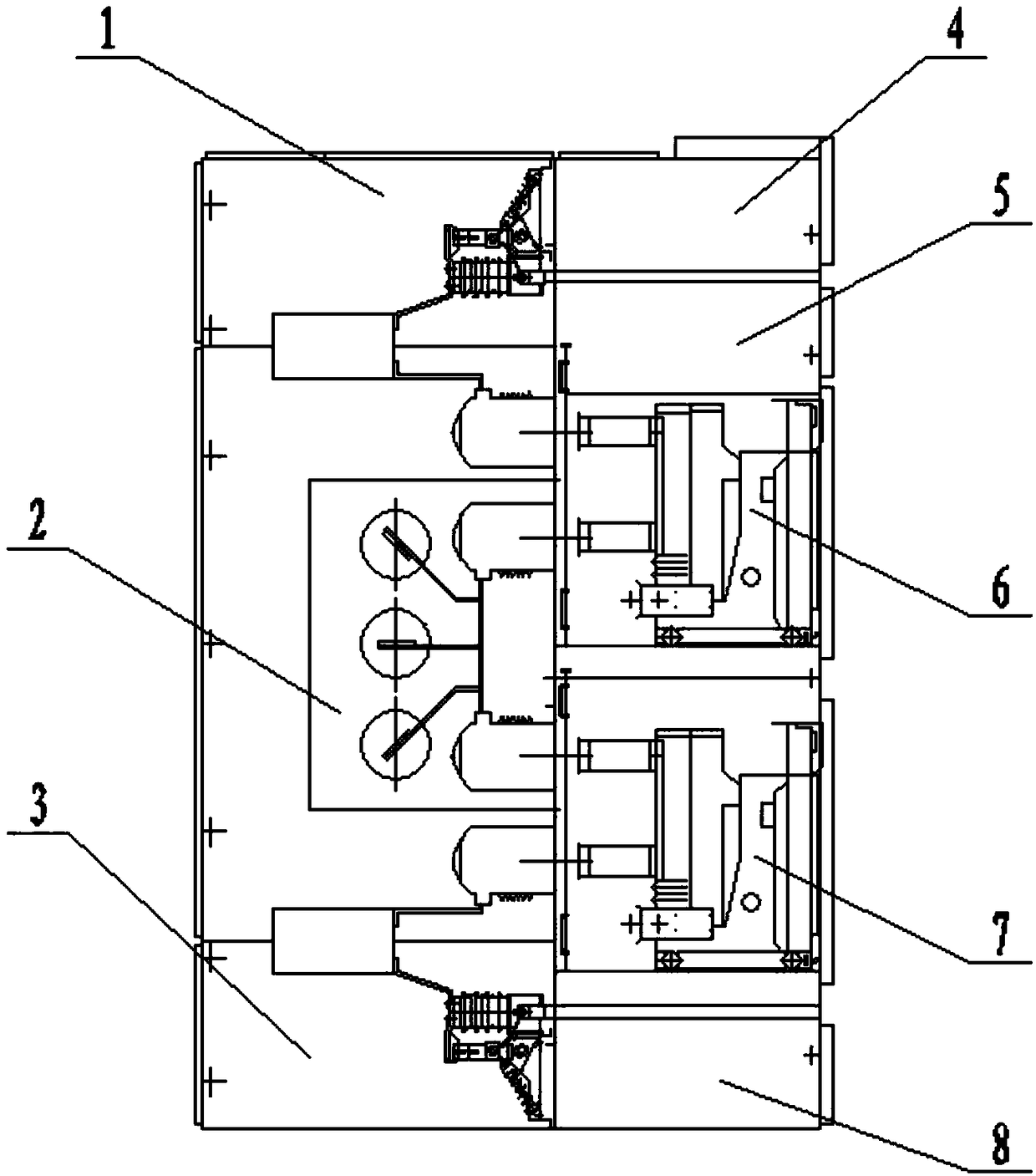
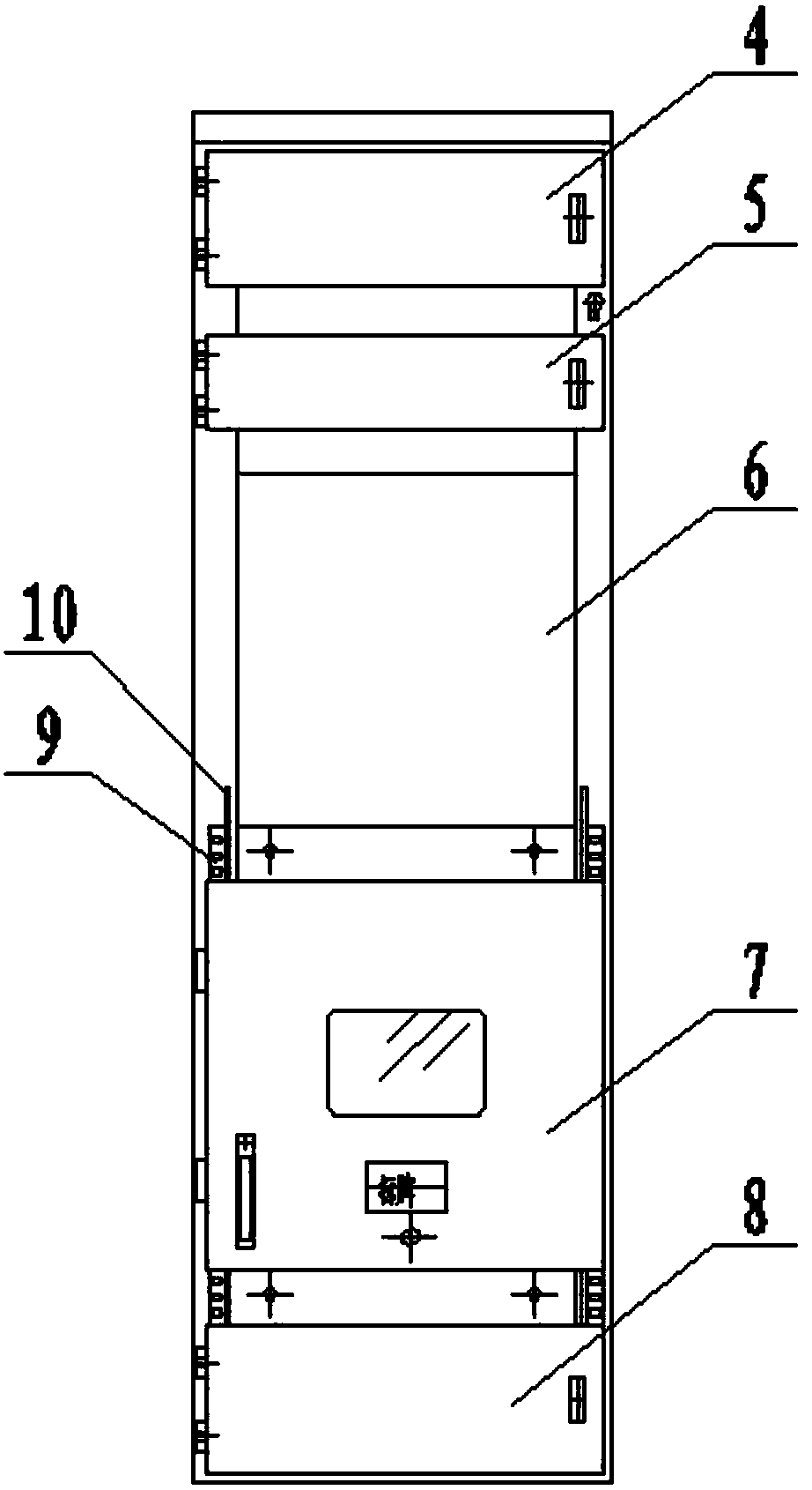
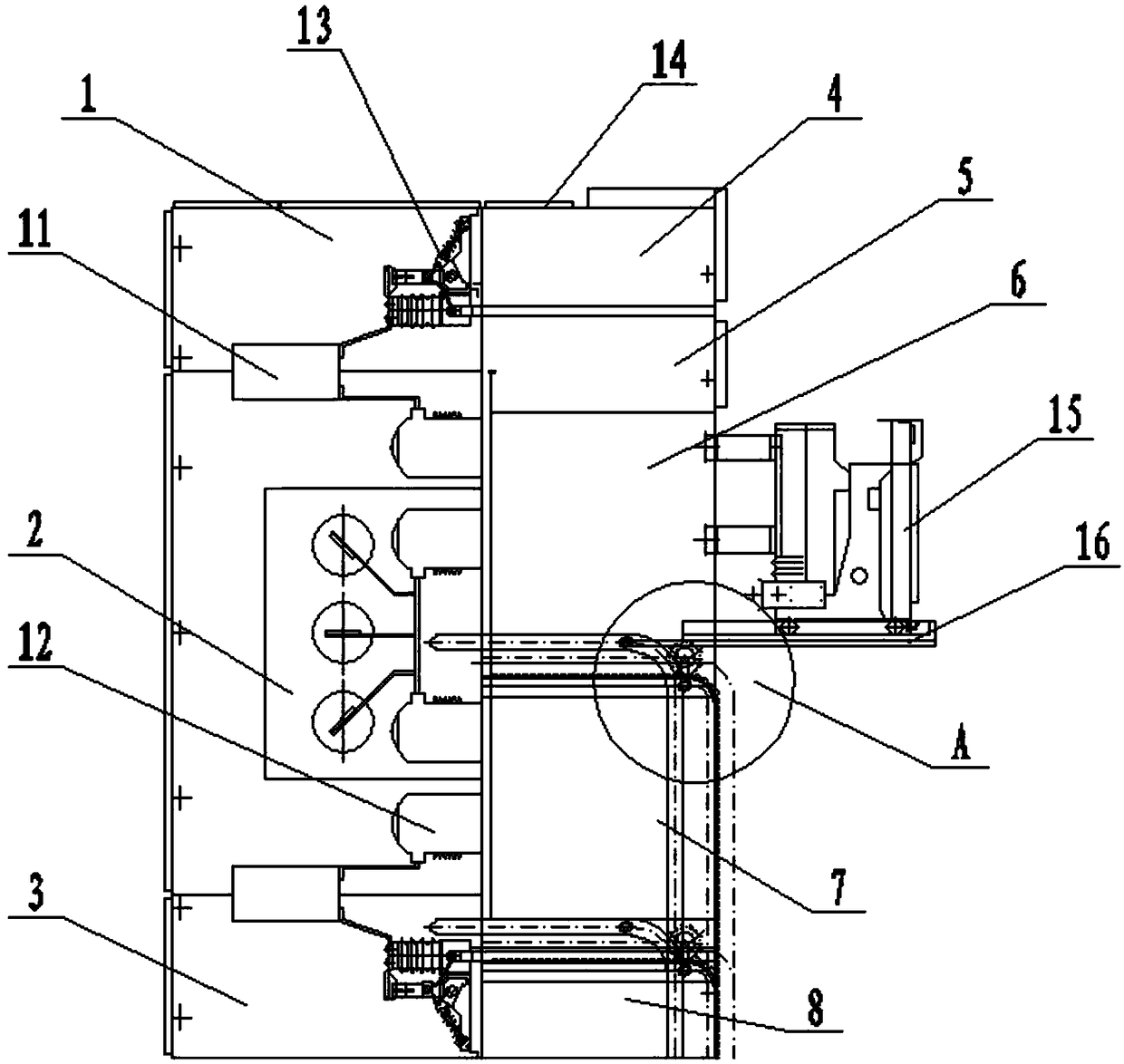
[0026] like figure 1 as shown, figure 1 and 2 As shown, a combined high-voltage switch cabinet includes a cabinet body and several electrical compartments, and the electrical compartments include an upper outlet room 1, a busbar room 2, a lower outlet room 3, a terminal row room 4, an upper instrument room 5, The upper handcart room 6, the lower handcart room 7 and the lower instrument room 8, the upper outlet room 1, the busbar room 2 and the lower outlet room 3 are arranged at the rear of the cabinet from top to bottom, and the cabinet door is connected with the cabinet by bolts ; The terminal row room 4, the upper instrument room 5, the upper handcart room 6, the lower handcart room 7 and the lower instrument room 8 are arranged in the front of the cabinet from top to bottom, one side of the cabinet door is hinged with the cabinet body, and the other side is set The door lock is connected to the cabinet body; the upper outlet room 1, the busbar room 2, the lower outlet ro...

Embodiment 2

[0035] The main structure of this embodiment is similar to Embodiment 1, and the operation method is the same, and the difference is that: Image 6 As shown, the driving wheel 20 is a sprocket, the track 9 is a chain, and the transmission device is a worm gear reducer 24 . Worm gear reducer 24 is mainly composed of transmission parts worm gear, shaft, bearing, box and its accessories, and can be divided into three basic structural parts: box, worm gear, bearing and shaft combination. The box body is the base of all accessories in the worm gear reducer 24, and is an important accessory to support and fix the shafting components, ensure the correct relative position of the transmission accessories and support the load acting on the reducer. The main function of the worm gear is to transmit the motion and power between the two interlaced shafts, and the main function of the bearing and the shaft is to transmit power, run and improve efficiency. Worm gear reducer 24 can realize s...


PUM


Abstract

The present invention discloses a combined high-voltage switch cabinet. The combined high-voltage switch cabinet comprises a cabinet body and a plurality of electrical compartments. Each electrical compartment comprises one upper outgoing line chamber, one bus chamber, one lower outgoing line chamber, one terminal board chamber, one upper instrument chamber, one upper handcart chamber, one lower handcart chamber and one lower instrument chamber. Trays are respectively arranged at the upper handcart chambers and the lower handcart chambers, and handcart switches in the upper handcart chambers and the lower handcart chambers are arranged on the trays. The combined high-voltage switch cabinet solve waste of spaces and cost of a high-voltage switch in the prior art, a breakthrough change is adapted to the high-voltage switch to allow the high-voltage switch cabinet to be more compact and move saving on the basis of ensuring safety and practicality, and to effectively reduce the installation and usage cost; and moreover, a track arranged at the cabinet body is employed to more conveniently and efficiently repair and replace handcarts in the switch, especially, the combined high-voltageswitch cabinet is suitable in a current social environment of an inch of land valuing an inch of gold.

Description

technical field [0001] The invention relates to the field of power supply and distribution, in particular to a combined high-voltage switch cabinet. Background technique [0002] At present, with the development of society, more and more high-power equipment is used around us. According to the reasoning of Ohm's law, under the same conditions, the higher the voltage, the smaller the reactive power loss, making high-voltage equipment more and more common. There are more and more things that need high-voltage control. It is inevitable that the high-voltage switchgear is used more and more frequently. Therefore, the high-voltage switchgear has become a relatively common power control device. Sometimes it is necessary to change the number of devices according to the needs of various aspects such as power distribution, so the required switches will change accordingly, and the number of switches that can control the power devices on the existing switch cabinets is fixed. It is pa...

Claims


Application Information

Patent Timeline
IPC IPC(8): H02B11/167
CPCH02B11/167
Inventor 魏怡琪
Owner 魏怡琪
Why Eureka
Try Eureka