
Peak demand reduction in mining haul trucks utilizing an on-board energy storage system

a technology of energy storage system and peak demand reduction, which is applied in the direction of locomotives, capacitors, electric devices, etc., can solve the problems of high peak power demand, voltage sag, and overload of electrical utility substations, so as to reduce peak power demand

Active Publication Date: 2013-08-06
INNOMOTICS LLC
View PDF10 Cites 11 Cited by
  • Summary
  • Abstract
  • Description
  • Claims
  • Application Information

AI Technical Summary

Benefits of technology

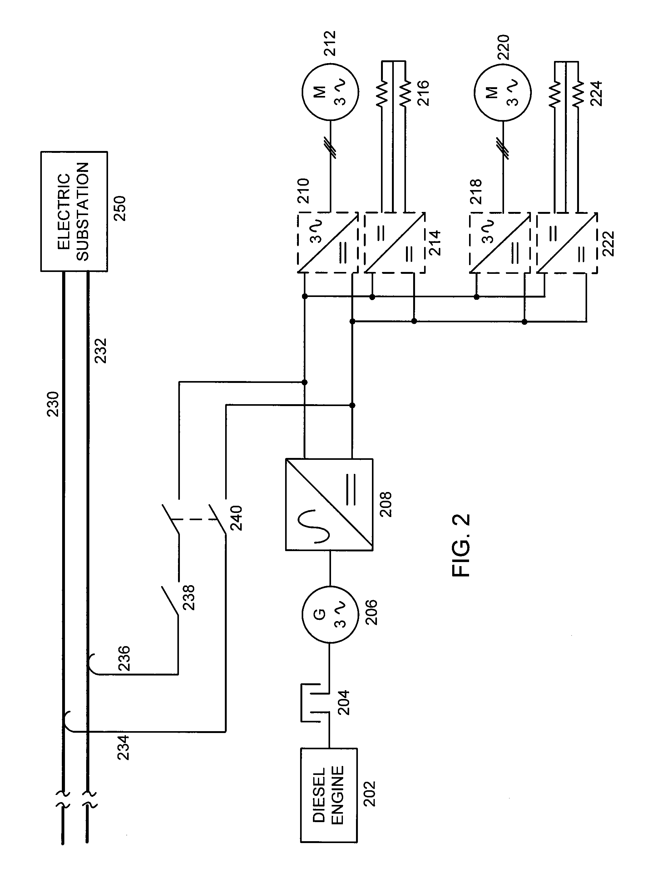
[0007]In an embodiment, electrical power from the on-board electrical energy system is used to reduce peak demand from the trolley power system. Electrical power supplied by the trolley power system is monitored. When the electrical power supplied by the trolley power system is less than or equal to a power limit, electrical power is supplied to the electrical motor only from the trolley power system. When the electrical power supplied by the trolley power system exceeds the power limit, electrical power is also supplied from the on-board electrical energy storage system. In an embodiment, the on-board electrical energy storage system comprises at least one ultracapacitor.

Problems solved by technology

High peak power demand has a negative impact on both the electrical utility company and the mining operator.
The high peak power demand may overload the electrical utility substation supplying electrical power to the trolley line.
Voltage sags, or even outages, may result.
High peak power demand may also overheat the trolley line cables and the pantograph contacts, leading to increased failure rates.

Method used


Image

  • Peak demand reduction in mining haul trucks utilizing an on-board energy storage system
  • Peak demand reduction in mining haul trucks utilizing an on-board energy storage system
  • Peak demand reduction in mining haul trucks utilizing an on-board energy storage system

Examples


Embodiment Construction

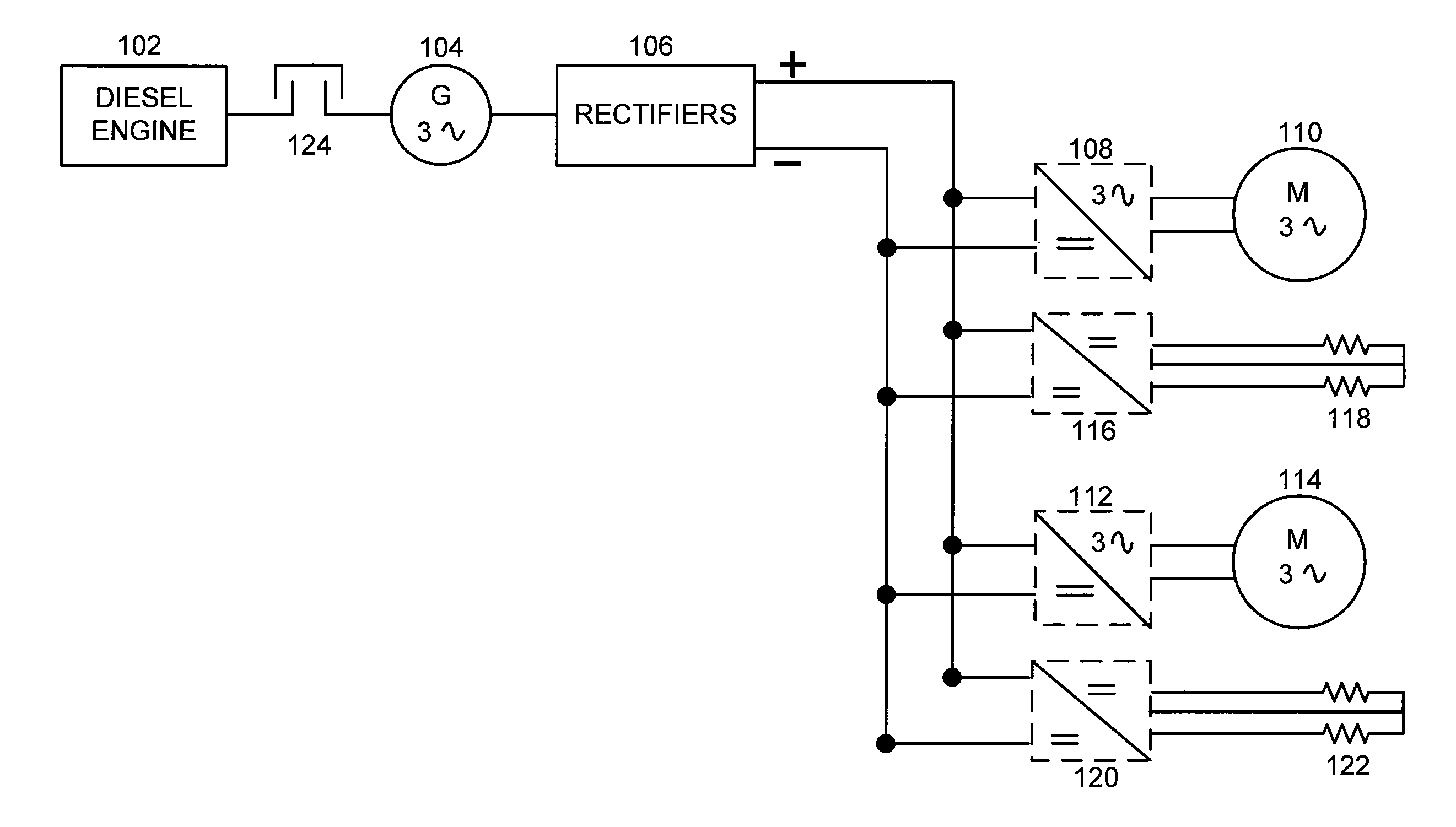
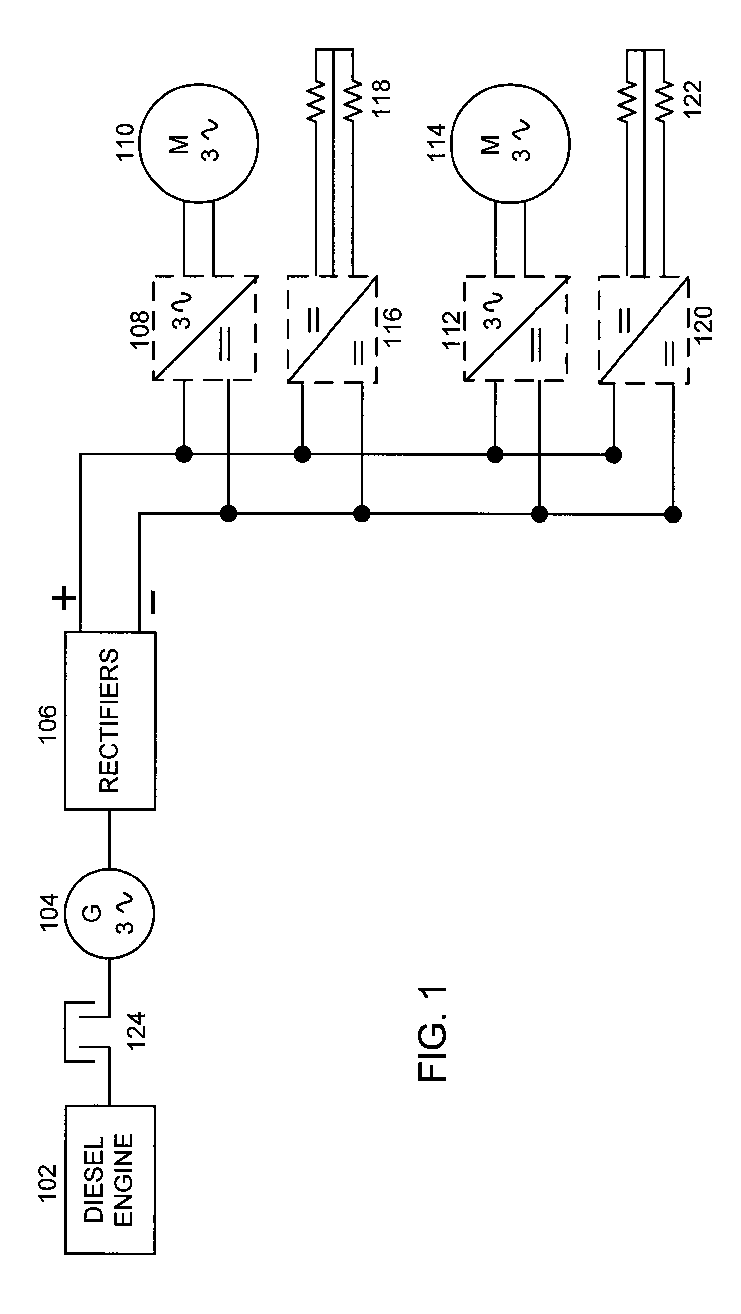
[0018]FIG. 1 shows a single-line diagram of a haul truck power system. The haul truck has two drive wheels. Each wheel is driven by a 3-phase alternating-current (AC) wheel motor (M). The wheel motors are referenced as wheel motor 110 and wheel motor 114. Electrical power is supplied by a diesel engine 102 driving a 3-phase AC generator (G) 104. (Other types of mechanical engines may be used; diesel engines are typical in mining operations.) Coupling 124 connects diesel engine 102 to generator 104. Diesel engine 102 and generator 104 are mounted on the haul truck. The AC output of generator 104 is fed into rectifiers 106. The direct current (DC) output of rectifiers 106 is fed into a set of inverters. Inverters 108 supply 3-phase AC power to wheel motor 110. Similarly, inverters 112 supply 3-phase AC power to wheel motor 114. Chopper 116 and power resistor grid 118 dissipate energy from wheel motor 110 during braking action. Similarly, chopper 120 and power resistor grid 122 dissipa...


PUM


Abstract

A mining haul truck driven by electrical wheel motors is powered by a trolley power system during an uphill climb. Retard energy captured during braking action on either the uphill climb or downhill descent is stored by an on-board electrical energy storage system. Electrical power is supplied from the on-board electrical energy storage system to reduce the peak power demand on the trolley power system during the uphill climb. One implementation of the on-board electrical energy storage system uses an ultracapacitor system.

Description

CROSS-REFERENCE TO RELATED APPLICATION[0001]This application is related to U.S. patent application Ser. No. 12 / 604,571, entitled System and Method for Reinjection of Retard Energy in a Trolley-Based Electric Mining Haul Truck, which is being filed concurrently herewith and which is herein incorporated by reference in its entirety.BACKGROUND OF THE INVENTION[0002]The present invention relates generally to power systems for mining haul trucks, and more particularly to peak demand reduction in mining haul trucks utilizing an on-board energy storage system.[0003]Mining haul trucks are typically equipped with electrical drive motors. Under some travel conditions, such as inside a mining pit, around a crusher, and on level surfaces, electrical power is supplied by an electrical generator powered by a diesel engine. Under more demanding conditions, such as travel on an uphill grade, electrical power is supplied by a trolley line. The haul truck draws electrical power from the trolley line ...

Claims


Application Information

Patent Timeline
Patent Type & Authority Patents(United States)
IPC IPC(8): B60L1/00B61C3/00B60L50/15
CPCB60L11/06B60L11/1801B60L11/1803Y02T10/7077Y02T10/70Y02T10/7005Y02T10/648B60L7/06B60L9/22B60L15/2009B60L2200/36B60L2210/10B60L2210/30B60L2210/40B60L2220/44B60L2220/46B60L2240/12B60L2240/14B60L2240/36B60L2240/425B60L2240/427B60L2240/429B60L2240/547B60L2240/549B60L50/40B60L50/12E21F17/06Y02T10/64Y02T10/72Y02T10/7072
Inventor MAZUMDAR, JOYKOLLNER, WALTER
Owner INNOMOTICS LLC
Learn More