
Illuminated keyboard

a keyboard and illuminated technology, applied in the field of illuminated keyboards, can solve the problems that the basic functions of the conventional illuminated keyboard, which fails to meet the user's requirements, and the conventional illuminated keyboard, which still has some drawbacks

Active Publication Date: 2013-08-06
PRIMAX ELECTRONICS LTD
View PDF6 Cites 73 Cited by
  • Summary
  • Abstract
  • Description
  • Claims
  • Application Information

AI Technical Summary

Benefits of technology

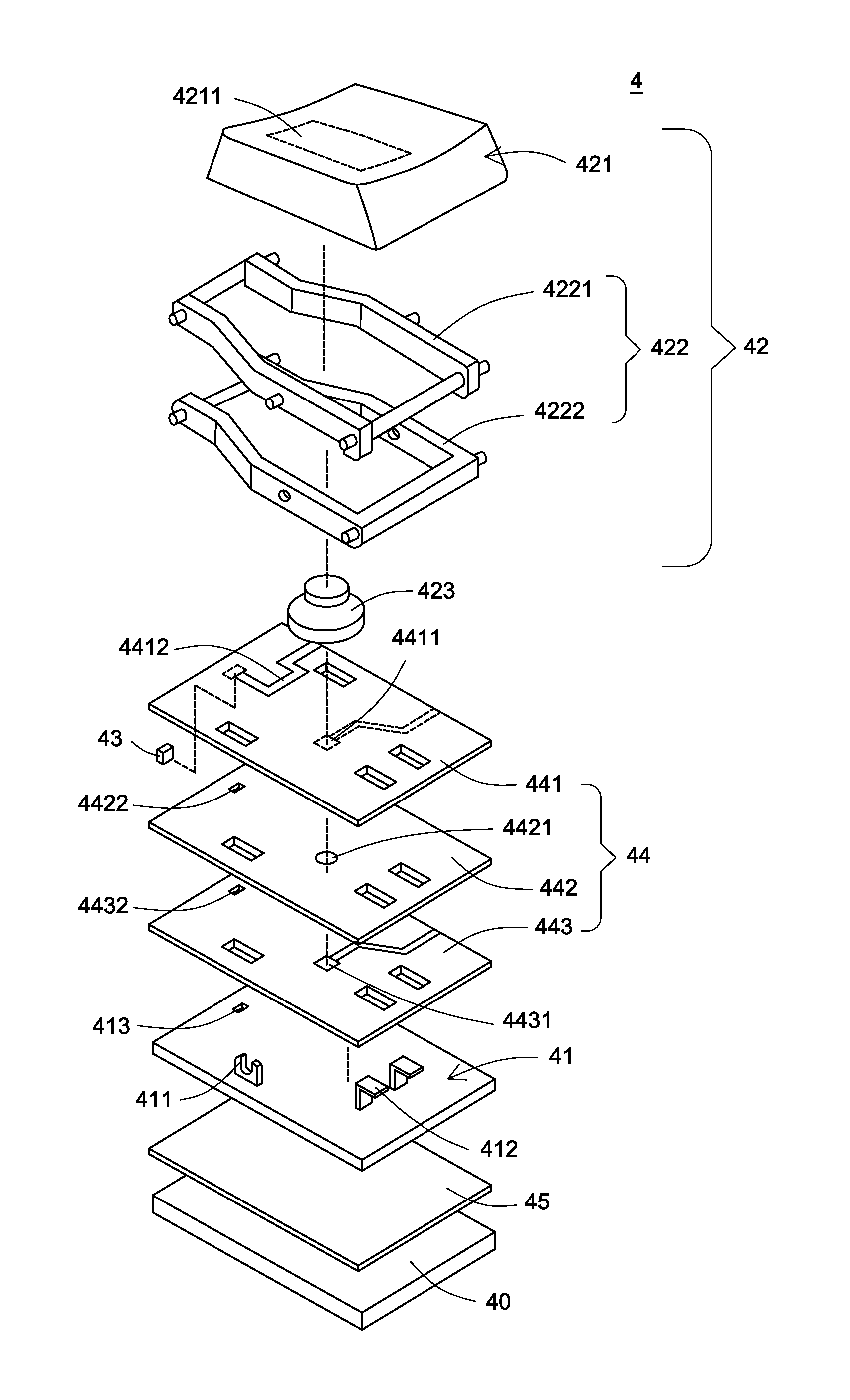
The present invention relates to an illuminated keyboard that provides more uniform lighting. The keyboard includes a transparent frame plate, a membrane switch circuit module, at least one key, a light source, and a light source film layer. The membrane switch circuit module includes an upper wiring board, a partition plate, and a lower wiring board. The light source film layer is arranged between the key and the supporting plate. The light source is connected with the light source circuit pattern to drive it and emit light. The keyboard also includes a supporting plate and a light-guiding film layer to guide the light beam. The key includes a keycap, a scissors-type connecting member, and an elastic element. The keycap has a light-transmissible region and the light source is connected with the keycap to sustain it. The invention provides an illuminated keyboard that provides more uniform lighting and improves the user's experience.

Problems solved by technology

With the maturity of computing technologies, the conventional keyboard 1 that has basic functions fails to meet the users' requirements.
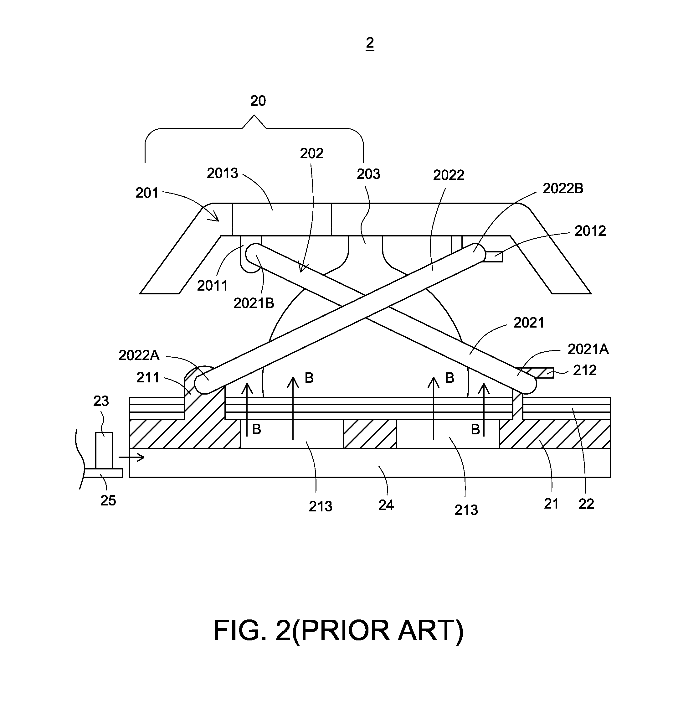
The conventional illuminated keyboard, however, still has some drawbacks.

Method used


Image

  • Illuminated keyboard
  • Illuminated keyboard
  • Illuminated keyboard

Examples


first embodiment

[0044]For obviating the drawbacks encountered from the prior art, the present invention provides an illuminated keyboard. FIG. 3 is a schematic view illustrating an illuminated keyboard according to the present invention. As shown in FIG. 3, the illuminated keyboard 3 comprises a supporting plate 30, a transparent frame plate 31, plural keys 32, a row of light sources 33 and a membrane switch circuit module 34. For clarification, only a light source 33 is shown in the drawing. The plural keys 32 are disposed on the membrane switch circuit module 34. The membrane switch circuit module 34 is disposed on the transparent frame plate 31. The transparent frame plate 31 is disposed on the supporting plate 30. An example of the light source 23 is a light emitting diode (LED). The number of light sources 33 is not equivalent to the number of keys 32. For the whole illuminated keyboard 3, the light beams emitted by the row of light sources 33 are sufficient to illuminate all of the keys 32.

[0...

second embodiment

[0073]It is noted that, however, those skilled in the art will readily observe that numerous modifications and alterations may be made while retaining the teachings of the invention. For example, like the second embodiment, an additional light-guiding film layer may be disposed between the supporting plate and the transparent frame plate. Alternatively, an additional light-guiding film layer may be arranged on the transparent frame plate.

[0074]From the above description, the transparent frame plate of the illuminated keyboard of the present invention has functions similar to the metallic base plate of the conventional illuminated keyboard, i.e. the function of connecting to the scissors-type connecting member. That is, through the scissors-type connecting member, the connection between the key and the transparent frame plate is similar to the connection between the key and the conventional metallic base plate. Moreover, since the transparent frame plate is made of a transparent mate...


PUM


Abstract

An illuminated keyboard includes a transparent frame plate, a key, a light source and a membrane switch circuit module. The light beam emitted by the light source is transmissible through the transparent frame plate. Consequently, the light source may be disposed on the membrane switch circuit module, between the key and the transparent frame plate, or under the transparent frame plate.

Description

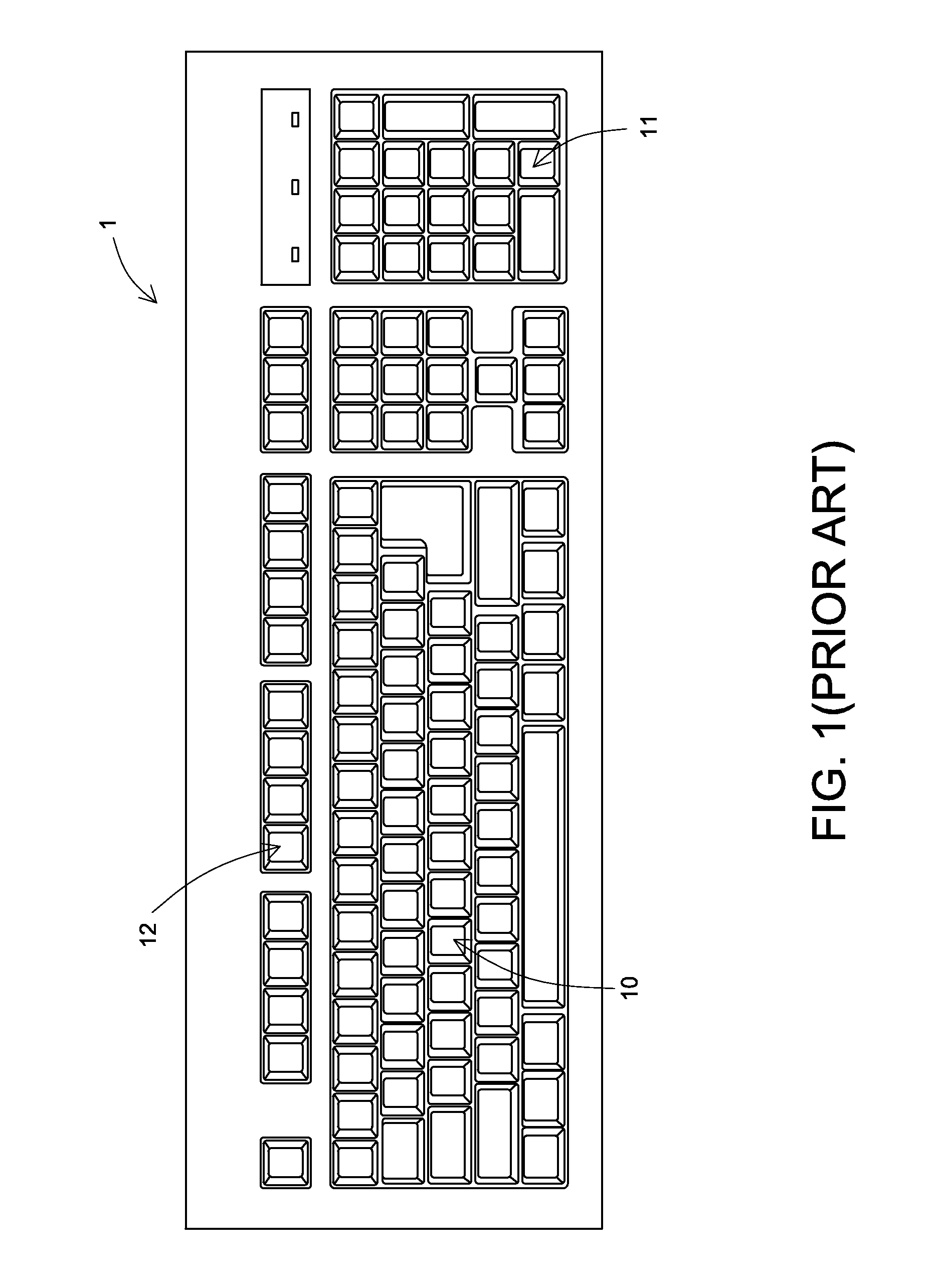
FIELD OF THE INVENTION[0001]The present invention relates to a keyboard, and more particularly to an illuminated keyboard with a luminous function.BACKGROUND OF THE INVENTION[0002]Generally, the common input device of a computer system includes for example a mouse, a keyboard device or a trackball. Via the keyboard device, the user may input characters and instructions into the computer system. As a consequence, most users and most manufacturers pay much attention to the development of keyboard devices.[0003]Hereinafter, the configurations and functions of a conventional keyboard device will be illustrated with reference to FIG. 1. FIG. 1 is a schematic view illustrating the outward appearance of a conventional keyboard device. The surface of the conventional keyboard device 1 includes plural keys. These keys include ordinary keys 10, numeric keys 11 and function keys 12. When one or more keys are pressed by the user, a corresponding signal is issued to the computer, and thus the co...

Claims


Application Information

Patent Timeline
Patent Type & Authority Patents(United States)
IPC IPC(8): H01H9/26
CPCH01H13/83H01H3/125H01H2203/026H01H2205/032H01H2209/026H01H2209/06H01H2209/082H01H2219/04H01H2219/06H01H2233/03
Inventor CHEN, BO-AN
Owner PRIMAX ELECTRONICS LTD
Learn More