
Membrane switch with rigid fascia

a technology of membrane switch and fascia, applied in the direction of contact surface shape/structure, electrical apparatus, contact, etc., can solve the problems of easy abrasion or damage, easy to be soft and susceptible to abrasion, and the common look and feel of thin plastic membrane can be limiting to designers, so as to reduce the deflection of the fascia and simplify the assembly

Inactive Publication Date: 2005-11-22
BROADCOM CORP +1
View PDF8 Cites 39 Cited by
  • Summary
  • Abstract
  • Description
  • Claims
  • Application Information

AI Technical Summary

Benefits of technology

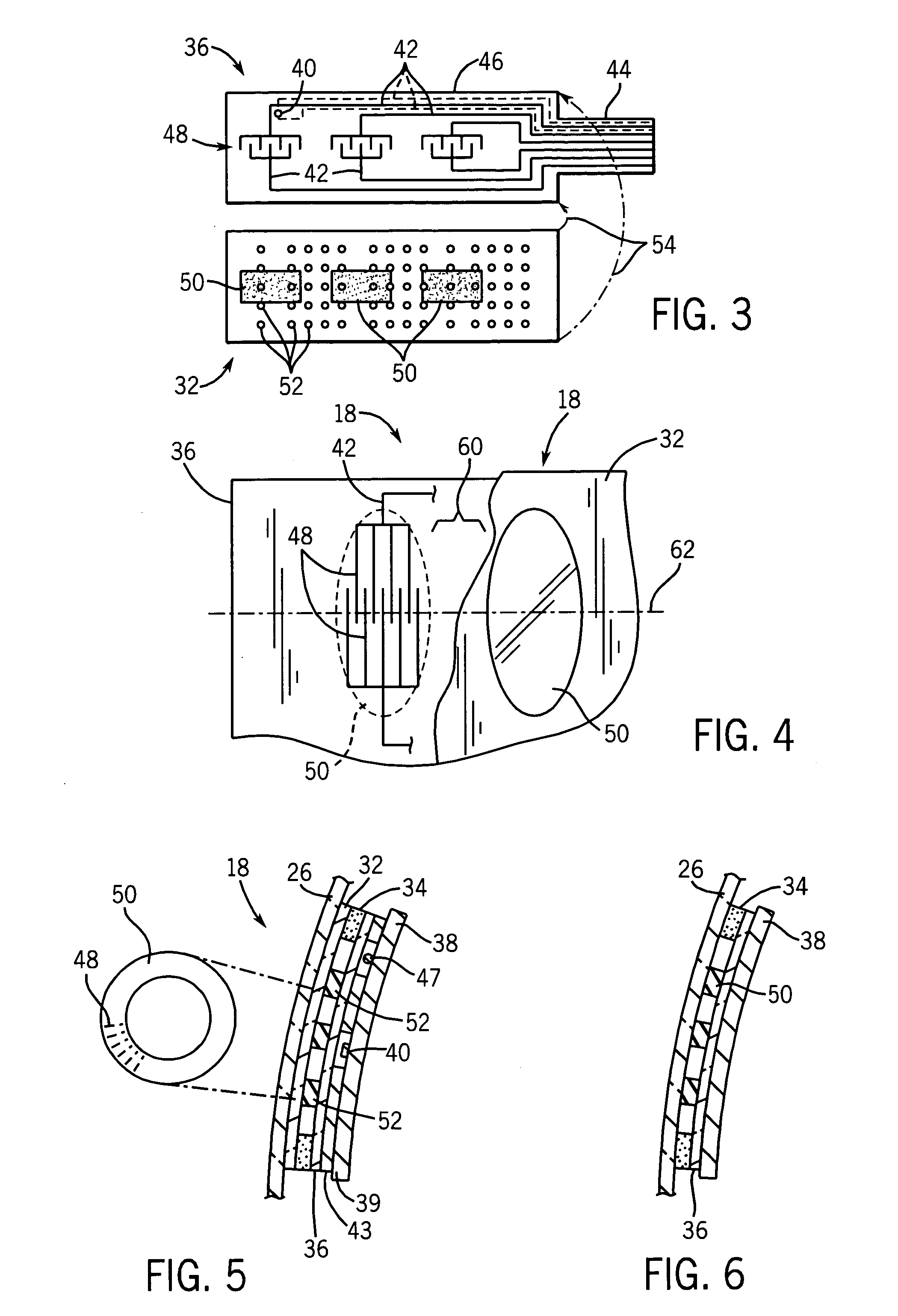
The present invention is a rigid fascia membrane switch that can work with or without mechanical structure between the fascia and the rest of the membrane switch to restrain the deflection of the fascia. It can be used with a variety of fascia materials and designs, including curved fascia. The switch uses an ultra-sensitive design with thin insulating dots, reducing the actuation force required to activate the switch and accommodating force-spreading by the fascia. The switch provides a simple assembly and is highly sensitive, allowing for easy actuation with minimal finger pressure. The front panel may be made of a rigid material, such as plastic or glass, and the switch can be integrated into flowing or curved designs without inset of a flat control panel. The printed insulator elements have a varying pattern density depending on their distance from the switch contacts, and the switch areas are separated along a first axis to accommodate force spreading while preserving desired switch spacings and contact areas.

Problems solved by technology

While the membrane itself is resistant to contamination and readily cleaned, it is soft and susceptible to abrasion or damage.
The common look and feel of thin plastic membrane can be limiting to designers experimenting with a wider range of design aesthetics.
As noted by Van Zeeland, the rigid panel tends to spread the force of actuation by a finger, or the like, over a broader area creating a risk that adjacent switches will be simultaneously actuated by a single touch.
Limiting the natural deflection of the front panel increases the force required to deflect the front panel to an amount which may be unacceptable to the average user.
The standoff system proposed by Van Zeeland also increases the complexity of manufacture of the membrane switch requiring specialized mechanical components that must be changed for each changed layout of the switch.
The problems of supporting these standoffs against the minor deflections they must resist presents additional barriers to the use of the Van Zeeland design.

Method used


Image

  • Membrane switch with rigid fascia
  • Membrane switch with rigid fascia
  • Membrane switch with rigid fascia

Examples


Embodiment Construction

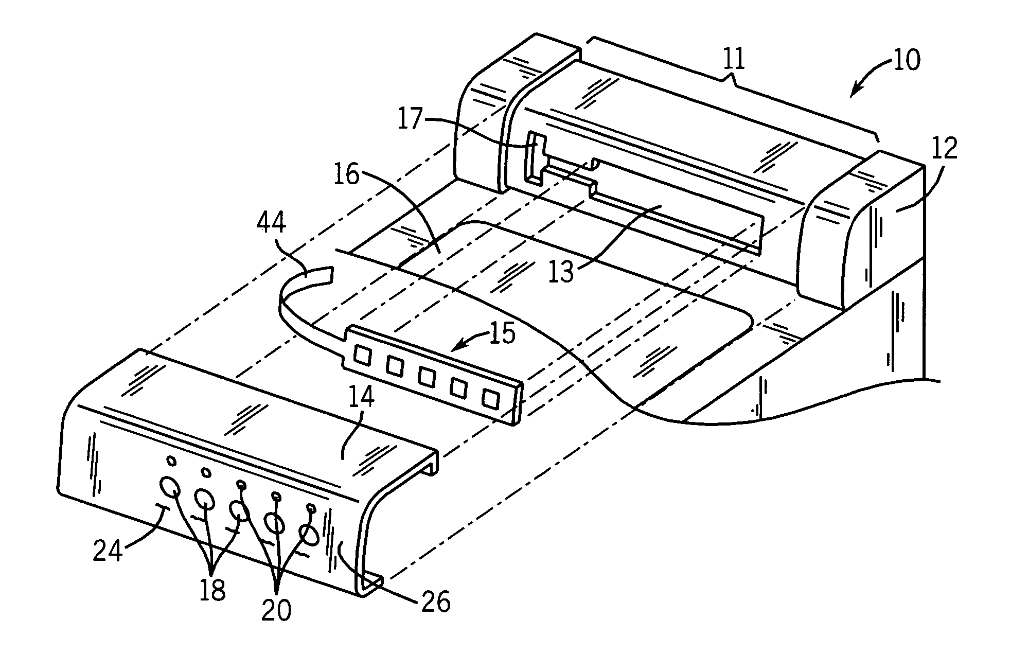
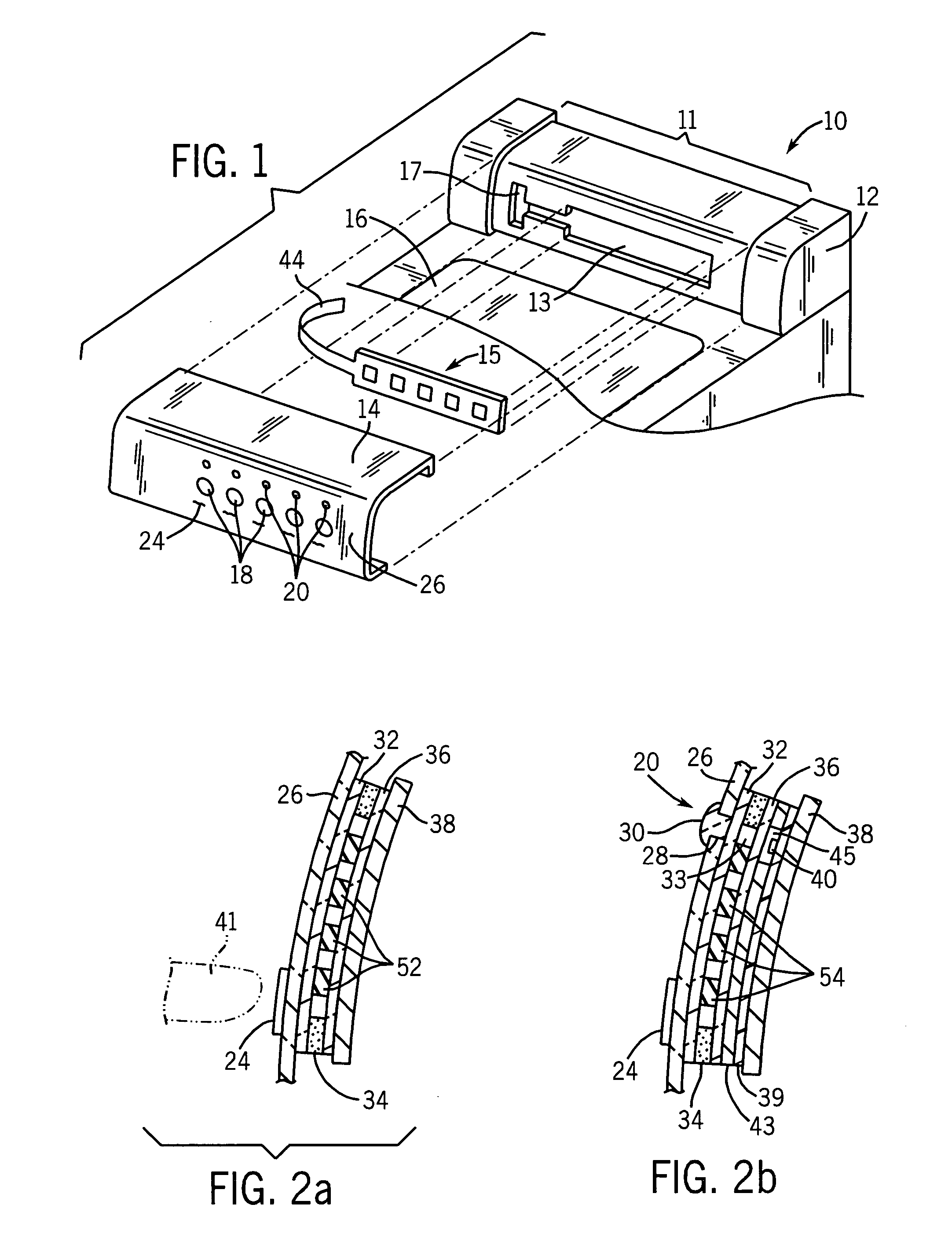
[0038]Referring now to FIG. 1, an appliance 10, for example, a top loading washing machine may provide a rearward upwardly extending console 12 having a fascia 14 facing the user from behind a tub access door 16 or the like.

[0039]The fascia 14 may be a metal cowling fitting over a recessed portion 11 of the console 12 to cover a recess 13 in a front face of the console 12 that provides a space for a membrane switch assembly 15 that will fit behind the control surface as will be described. The membrane switch assembly 15 provides a tail 44 that may pass through an opening 17 through the front face of the console 12 to connect the membrane switch assembly 15 to control electronics (not shown) positioned within the console 12.

[0040]The fascia 14 may be outwardly convex, for example, formed of 0.019-inch thick aluminum sheet supported by the console 12. The fascia 14 is a rigid material, meaning generally that it retains its shape without support and is much stiffer than a conventional ...


PUM


Abstract

A membrane switch provides a substantially rigid front fascia without the need for flexure limiting standoffs or the like. The membrane switch may use thin, printed insulating dots whose pattern controls the force required to actuate the switch elements as a function of distance from the switch elements preventing multiple activations.

Description

CROSS-REFERENCE TO RELATED APPLICATIONS[0001]This application is based on and claims the benefit of U.S. Provisional application 60 / 504,921 filed Sep. 22, 2003, and U.S. Provisional application 60 / 520,206 filed Nov. 14, 2003, both hereby incorporated by reference.STATEMENT REGARDING FEDERALLY SPONSORED RESEARCH OR DEVELOPMENTBACKGROUND OF THE INVENTION[0002]The present invention relates to electrical membrane switches and in particular to a membrane switch having or adhered to a substantially rigid front surface or fascia.[0003]Membrane switches are well known in the art and normally employ a pair of stacked flexible membranes having opposed contacts printed on their facing surfaces. A spacer layer separates the membranes, except at a region about the contacts, allowing pressure from a finger or the like to deform one of the membranes so that its contact touches the contact of the other membrane closing an electrical switch. The natural resilience of the membranes may separate the c...

Claims


Application Information

Patent Timeline
Patent Type & Authority Patents(United States)
IPC IPC(8): H01H13/70H01H13/702
CPCH01H13/702H01H2209/006H01H2209/018H01H2209/07H01H2209/084H01H2239/038
Inventor HOWIE, MALCOLMHUANG, JIIANMING
Owner BROADCOM CORP
Learn More