Process chamber and method for processing a material by a directed beam of electromagnetic radiation, in particular for a laser sintering device

Active Publication Date: 2014-11-25
EOS ELECTRO OPTICAL SYST
View PDF34 Cites 50 Cited by
  • Summary
  • Abstract
  • Description
  • Claims
  • Application Information

AI Technical Summary

Benefits of technology

[0009]The device according to the present disclosure has the advantage that the lower gas flow is directed away from the coupling window. Thereby it is possible to improve the separation of the dirt-loaded gas, which rises from the processing surf

Problems solved by technology

This leads to a reduction of the transparency of the coupling window and accordingly to a decrease of the intensity of the laser beam.
However, in the known device the surface of the coupling window does not stay clean all over.
Also, temperature gradients between the coupling window and the blowing gas on the

Method used


Image

  • Process chamber and method for processing a material by a directed beam of electromagnetic radiation, in particular for a laser sintering device
  • Process chamber and method for processing a material by a directed beam of electromagnetic radiation, in particular for a laser sintering device
  • Process chamber and method for processing a material by a directed beam of electromagnetic radiation, in particular for a laser sintering device

Examples


Example

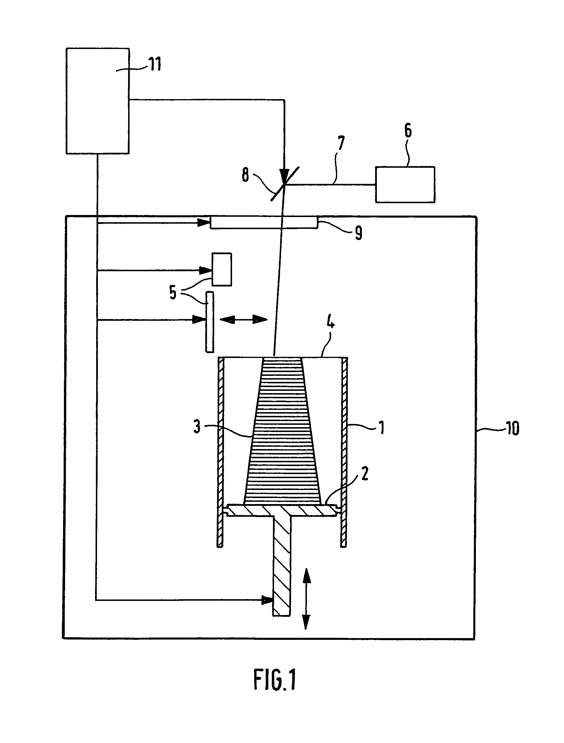
[0013]FIG. 1 shows a laser sintering device, which is an embodiment of a device for a layer-wise manufacturing of a three-dimensional object. The laser sintering device comprises a container 1, which is open to the top and has a support 2 that can be moved in it in a vertical direction and supports the object 3 to be formed. The support 2 is adjusted in a vertical direction such that a layer of the object to be solidified at a time lies within a working plane 4. Further, an application device 5 for applying the building material, which is in powder form and can be solidified by electromagnetic radiation, is provided. Also, the device comprises a laser 6. The laser beam 7, which is generated by the laser, is directed to a coupling window 9 by means of a deflection device 8 and is transmitted by the coupling window 9 into the process chamber 10 and is focussed in a predetermined point within the working plane 4.

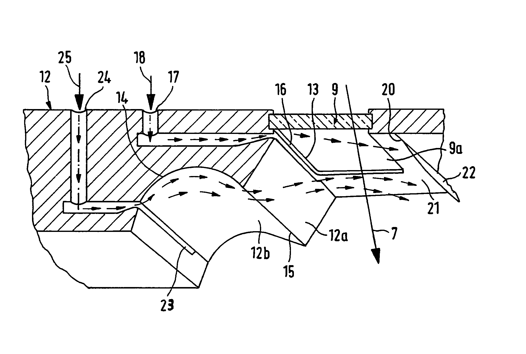
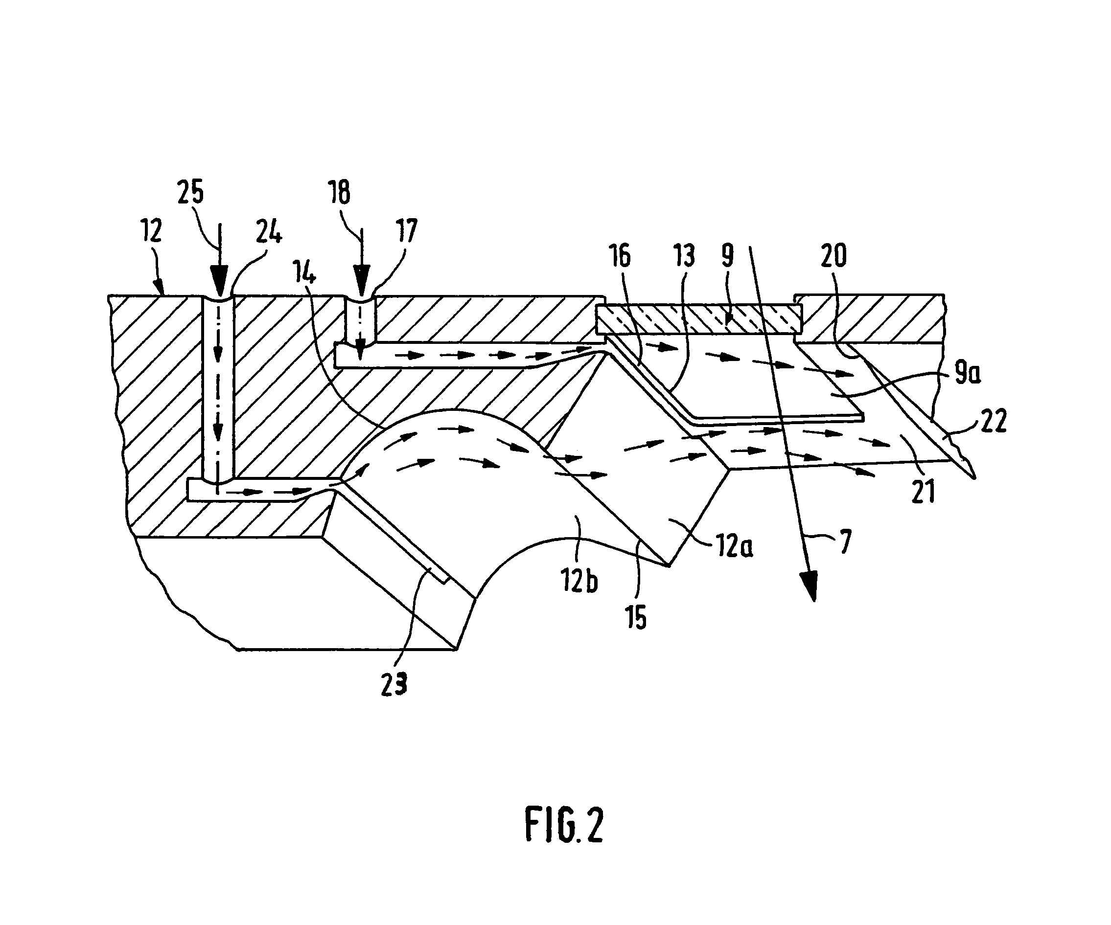
[0014]For instance the coupling window 9 may be provided in the top wall o...


PUM

PropertyMeasurementUnit
Angleaaaaaaaaaa
Flow rateaaaaaaaaaa

Abstract

A process chamber for a processing of a material by means of a directed beam of electromagnetic radiation is provided, which comprises an optical element (9) for coupling the beam (7) into the process chamber (10), wherein the optical element has a surface (9a) facing the inside of the process chamber, a wall section (12) surrounding the optical element (9), a first inlet (16) for a gas that is arranged at one side of the optical element (9) and designed such that an escaping first gas flow (18) strokes substantially tangentially over the surface (9a) of the optical element (9), a second inlet (23) for a gas, which is designed and arranged such that an escaping second gas flow (25) flows at a distance to the surface (9a) in substantially the same direction as the first gas flow (18).

Description

BACKGROUND OF THE INVENTION[0001]The invention is related to a process chamber and a method for processing a material by a directed beam of electromagnetic radiation, in particular for a laser sintering device.[0002]A laser sintering device comprises in a known manner a laser and a process chamber, in which the object to be manufactured is built, as well as a coupling window for coupling the laser beam into the process chamber.[0003]When the laser locally hits the powder material and when the powder material is heated, an evaporation of small amounts of material may occur. In the process the evaporated material or constituents of the same or also chemical reaction products as well as dust particles suspended in the atmosphere of the process chamber deposit at the coupling window. This leads to a reduction of the transparency of the coupling window and accordingly to a decrease of the intensity of the laser beam.[0004]From WO 97 / 06918 a laser sintering device is known, in which a noz...

Claims


Application Information

Patent Timeline
IPC IPC(8): B23K26/00B29C67/00B23K26/12B22F3/105B23K26/14
CPCB23K26/12B23K26/1464B29C67/0077B22F3/1055B23K26/123B22F3/003B23K26/127B22F2003/1056B22F2998/00B29C64/153Y02P10/25B22F10/28B22F10/322B22F12/70B22F12/44B22F10/32
Inventor PERRET, HANSPHILIPPI, JOCHEN
Owner EOS ELECTRO OPTICAL SYST
Why Eureka
Try Eureka