Sprayer with remotely pivotable and selectively lockable nozzle

A sprayer, nozzle technology applied in the field of sprayers with nozzles pivotable at the distal end and selectively lockable, able to solve problems such as difficulties

Active Publication Date: 2012-11-28
HYDE TOOLS
View PDF14 Cites 18 Cited by
  • Summary
  • Abstract
  • Description
  • Claims
  • Application Information

AI Technical Summary

Problems solved by technology

Another difficulty encountered by users of certain embodiments constructed in accordance with the '644 patent is that although the user may attempt to hold the slidable or rotatable actuator in a fixed position so as to resist rotation of the nozzle, for some users In other words, this can prove difficult when the trigger is squeezed and the fluid is allowed to flow
More specifically, for example, in versions where the actuator is also a handle, once the pressurized fluid is flowing, a user attempting to counteract the recoil and thrust inadvertently causes the actuator to move and thus rotate the nozzle's spray angle to an undesired The change

Method used


Image

  • Sprayer with remotely pivotable and selectively lockable nozzle
  • Sprayer with remotely pivotable and selectively lockable nozzle
  • Sprayer with remotely pivotable and selectively lockable nozzle

Examples


Embodiment Construction

[0023] The following descriptions of various embodied fluid sprayers are illustrative in nature and are not intended to limit the application of the invention or its use. Accordingly, the various embodiments, aspects, versions and examples described in the Summary and Detailed Description are non-limiting examples in nature which fall within the scope of the appended claims and are not intended to limit the broadest scope of the claims .

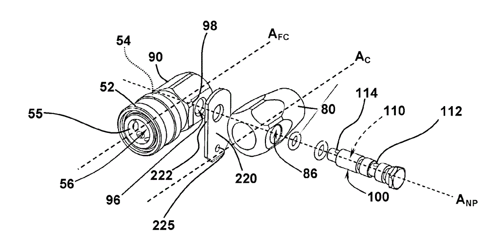
[0024] see figure 1 , the illustrative nebulizer 10 includes a rigid fluid conduit 20 along the conduit axis A C Extends between longitudinally opposite first and second conduit ends 22 , 24 . The conduit sidewall 26 has an outer surface 27 and an inner surface 28 that define an inner fluid passageway 40 extending between the first conduit end 22 and the second conduit end 24 . First conduit end 22 and second conduit end 24 respectively include a fluid inlet opening 42 through which fluid can be introduced into fluid passageway 40 and a f...


PUM


Abstract

A fluid sprayer includes a rigid fluid conduit with a conduit side wall extending along a conduit axis between open first and second conduit ends. The conduit side wall defines a fluid passage extending between the open first and second ends. A spray nozzle with a fluid-expulsion bore is connected to the second conduit end such that it can pivot about a nozzle-pivot axis that extends orthogonally to the conduit axis and such that fluid introduced into the first conduit end is expelled through the fluid-expulsion bore. A nozzle actuator is attached to the conduit for bi-directional rotation about an actuator-rotation axis having a component of spatial extension perpendicular to the conduit axis. The nozzle actuator and nozzle are mechanically linked so that rotation of the actuator causes the nozzle to pivot with respect to the conduit axis. A spray-angle selector rotates in tandem with the nozzle actuator and includes an angle-selection surface. A selector stop, with a base portion fixed relative to the fluid conduit, cooperatively engages the angle-selection surface to define a plurality of angular nozzle positions and provide resistance opposing pivotal movement out of each angular nozzle position.

Description

Background technique [0001] While not limiting the application or scope of the present invention, embodiments of the present invention are particularly well suited for implementation in the spray gun portion of pressure washers and paint sprayers. Sprayers and associated nozzles are configured for a variety of purposes including applying "atomized" paint and washing objects with high velocity discharges of water. The latter type of equipment is commonly referred to as a "pressure washer". Pressure washers can be used to clean cars, houses, and other objects or structures. There are instances where users of typical pressure washers are unable to position the nozzle at an angle sufficient to spray the desired target. For example, a user may wish to spray salt and sand from under the wheel wells of a car to prevent corrosion. However, the handle or "wand" portion of a typical pressure washer is too large for the user to spray from under the wheel well in the area directly abov...

Claims


Application Information

Patent Timeline
Patent Type & Authority Applications(China)
IPC IPC(8): B05B15/08B05B15/68
CPCB05B15/066B60S3/047B08B3/026B05B15/652
Inventor B.巴克斯特W.R.巴克纳姆R.M.法兰德C.塔尔博特
Owner HYDE TOOLS
Why Eureka
Try Eureka