Rotational Speed Sensor Having A Coupling Bar

a technology of rotating speed sensor and coupling bar, which is applied in the direction of acceleration measurement using interia force, turn-sensitive devices, instruments, etc., can solve the problems of affecting the measurement, the coupling of seismic masses by means of the proposed coupling unit is sensitive to parallel interference excitation in the measuring direction, etc., to avoid or reduce parasitic modes and interference deflections

Active Publication Date: 2010-02-18
CONTINENTAL TEVES AG & CO OHG
View PDF9 Cites 45 Cited by
  • Summary
  • Abstract
  • Description
  • Claims
  • Application Information

AI Technical Summary

Benefits of technology

[0008]An object of the present invention is to avoid or reduce pa

Problems solved by technology

The seismic masses are suspended directly from the substrate, with this suspension being embodied in such a way that it has to ensure the possibility of deflection of the seismic masses both for the drive and reading modes of the rotational speed sensor, as a result of which undesired cross

Method used


Image

  • Rotational Speed Sensor Having A Coupling Bar
  • Rotational Speed Sensor Having A Coupling Bar
  • Rotational Speed Sensor Having A Coupling Bar

Examples


Embodiment Construction

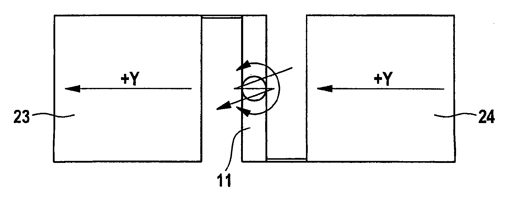
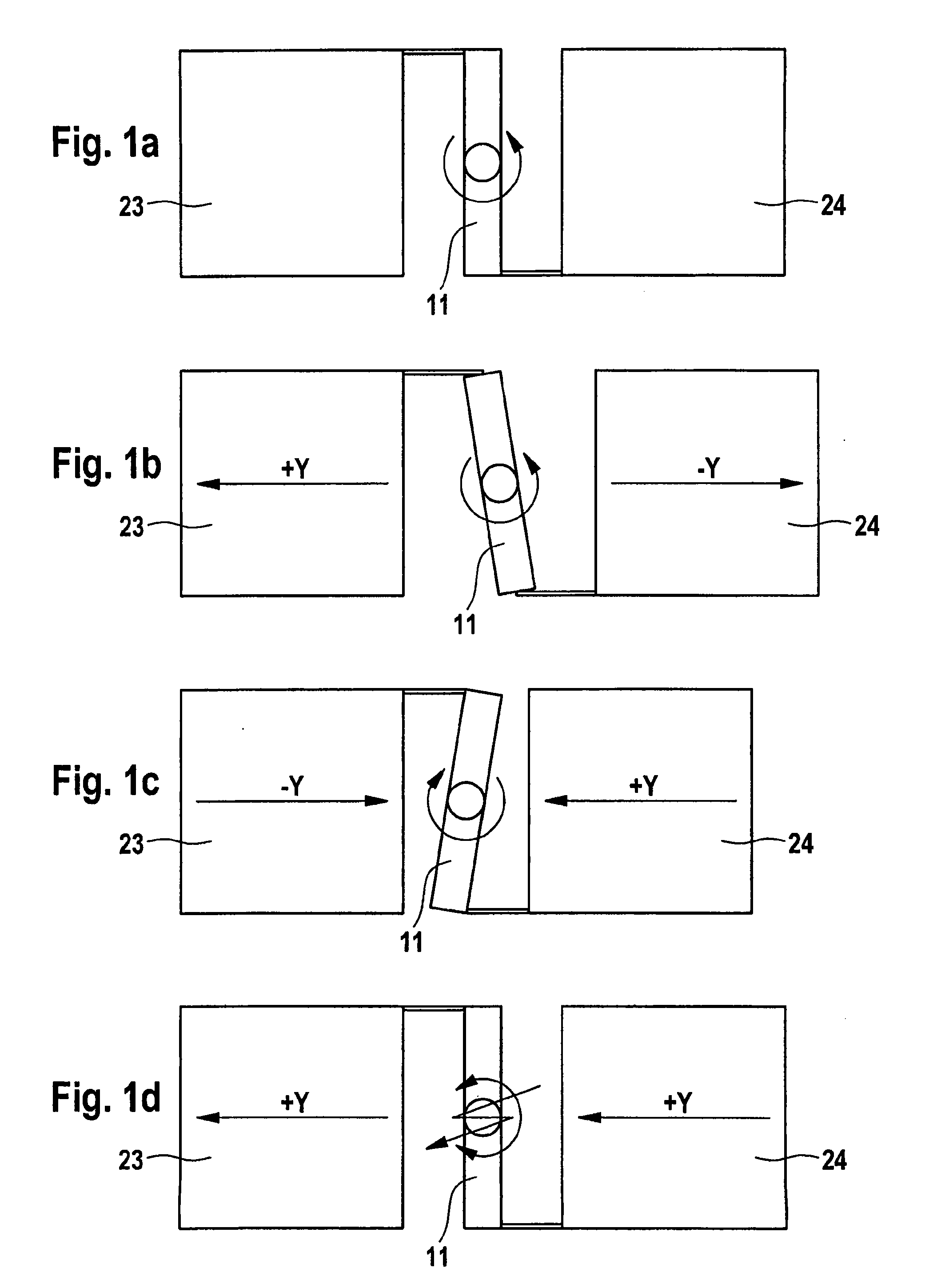
[0070]FIG. 1a shows the suspension diagram of a rotationally suspended rigid coupling bar 11 which suppresses or prevents undesired common-phase deflections of the seismic masses 23 and 24 in the drive mode. In the drive mode, seismic masses 23 and 24 oscillate with respect to one another in antiphase in the y direction. FIG. 1b illustrates here the method of functioning of the coupling bar as the seismic masses move apart from one another, while FIG. 1c shows the corresponding coupling principle when the seismic masses 23 and 24 move toward one another. When the seismic masses 23 and 24 move apart from one another or toward one another, the coupling bar 11 is therefore deflected rotationally, specifically about the z axis. FIG. 1d illustrates the method of functioning of the coupling bar 11 in the case in which the seismic masses 23 and 24 wish to move in the same direction, in this case both wish to move in the y direction to the left, owing, for example, to interference. This mov...


PUM

PropertyMeasurementUnit
Speedaaaaaaaaaa
Gravityaaaaaaaaaa

Abstract

A rotational speed sensor including at least one substrate, at least two base elements which each have a frame, a means for suspending the frame from the substrate, at least one seismic mass and one means for suspending the seismic mass from the frame. One or more drive means are provided for driving one or more base elements and one or more reading devices. The at least two base elements are coupled to one another by means of at least one coupling bar.

Description

CROSS-REFERENCE TO RELATED APPLICATIONS[0001]This application is the U.S. national phase application of PCT International Application No. PCT / EP2007 / 052304, filed Mar. 12, 2007, which claims priority to German Patent Application No. DE102006011572.4, filed Mar. 10, 2006 and German Patent Application No. DE102007012163, filed Mar. 12, 2007, the contents of such applications being incorporated by reference herein in their entirety.BACKGROUND OF THE INVENTION[0002]1. Field of the Invention[0003]The invention relates to a rotational speed sensor, a method for manufacturing a rotational speed sensor and to the use of the rotational speed sensor in motor vehicles.[0004]2. Description of the Related Art[0005]Rotational speed sensors are generally used to sense the angular speed of a system about a defined axis. An important field of application of rotational speed sensors is automobile engineering, for example in vehicle movement dynamics control systems such as the electronic stability pr...

Claims


Application Information

Patent Timeline
IPC IPC(8): G01C19/56H05K3/00G01C19/5684
CPCG01C19/5712Y10T29/49124G01P15/0888G01C19/574G01C19/56G01P3/42
Inventor GUNTHNER, STEFANHARTMANN, BERNHARD
Owner CONTINENTAL TEVES AG & CO OHG
Why Eureka
Try Eureka