Sensor

a technology of sensors and capacitors, applied in the field of sensors, can solve the problems of corresponding damage, change in capacitance difference between these two capacitors, and greater deflection of moving parts, and achieve the effect of smooth manner and good deceleration

Inactive Publication Date: 2005-08-02
ROBERT BOSCH GMBH
View PDF10 Cites 26 Cited by
  • Summary
  • Abstract
  • Description
  • Claims
  • Application Information

AI Technical Summary

Benefits of technology

[0006]The exemplary embodiments(s) of the present invention provide two ways to allow the impact forces in a sensor of the type named at the beginning to be reduced, in order to prevent conchoidal breaks and related incipient damage to the sensor structure as well as particle formation.
[0007]This is achieved according to the exemplary embodiment of the present invention in part by the fact that a stop for a moving part of the sensor structure, which functions as an overload protection device, is of a flat design, so that in the event of a corresponding overload acceleration contact between the moving part and this stop occurs via a flat surface. This enables the impact forces to be distributed to the sensor structure and absorbed by it more uniformly.

Problems solved by technology

An acceleration acting on the sensor structure causes the rocker to rotate or tilt around the spring system, thus causing a change in the difference of capacitances between these two capacitors.
Overload accelerations may also result in greater deflections of the moving parts, however, and thus to corresponding damage.
In the first of these cases the motion of the torsion spring and of the seismic mass is easily limited by a stop at an electrically neutral location on the substrate.
Hence in the case of a structural height of around 10 μm, deflections of 10 μm or more may result in the seismic mass being elevated out of its surroundings, and consequently in the sensor structure getting stuck.
Such conchoidal breaks may modify the mechanical properties of the spring system or result in development of cracks as incipient damage to the sensor structure.
This may cause changes to the characteristics of the sensor such as sensitivity, offset and test signal.
Furthermore, conchoidal breaks are a source of particles that may cause electrical short circuits or also mechanical blocking of the rocker.
On the whole, the aforementioned conchoidal breaks usually result in quality-relevant degradation of the sensor function, and in extreme cases may even result in total failure of the sensor function.

Method used


Image

  • Sensor
  • Sensor
  • Sensor

Examples


Embodiment Construction

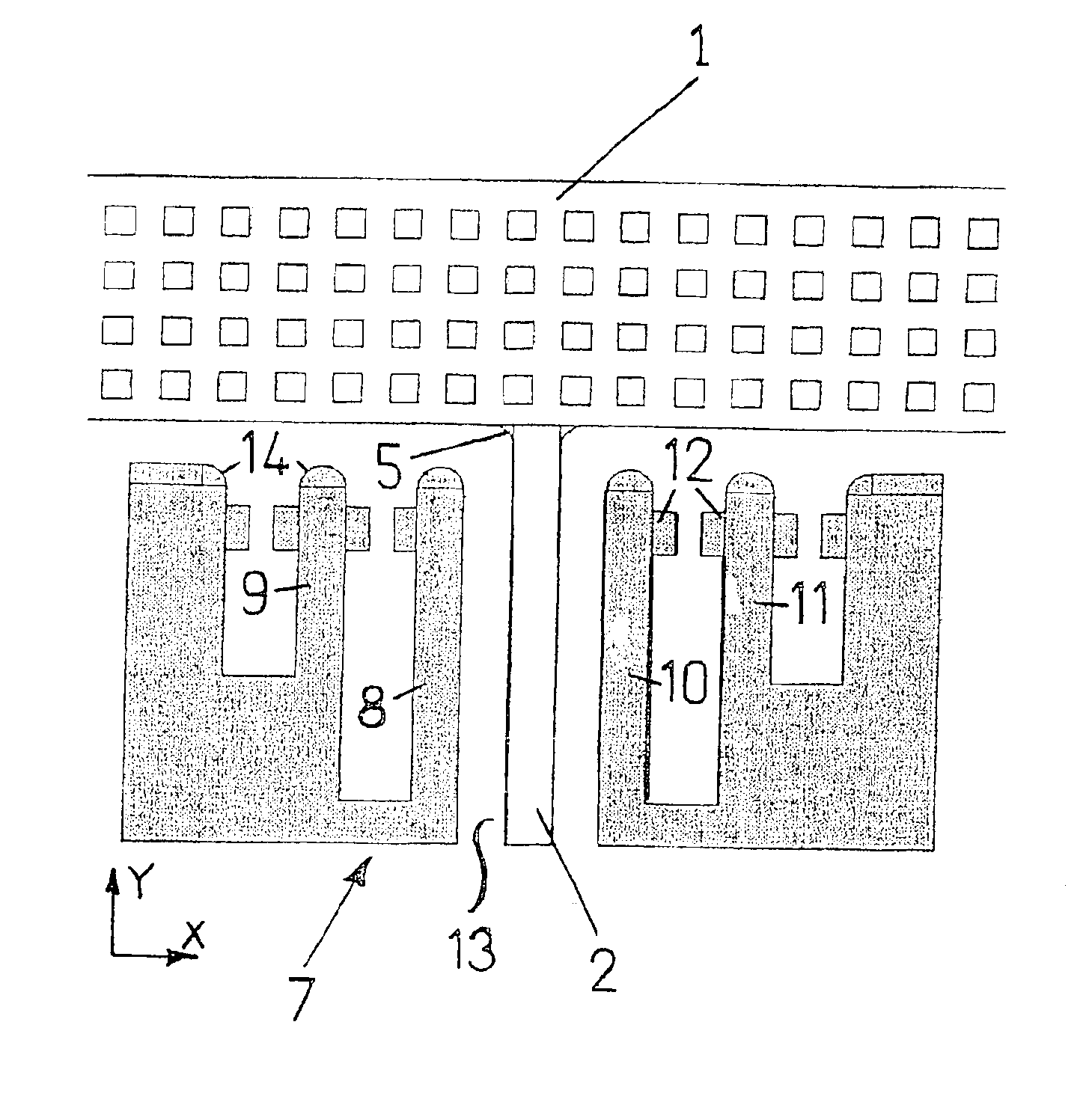
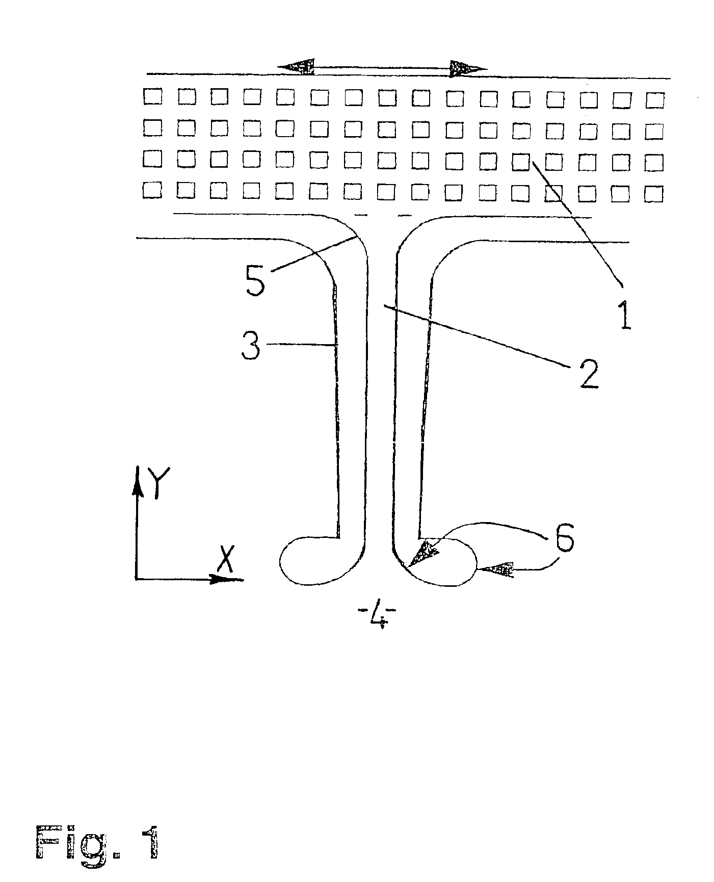
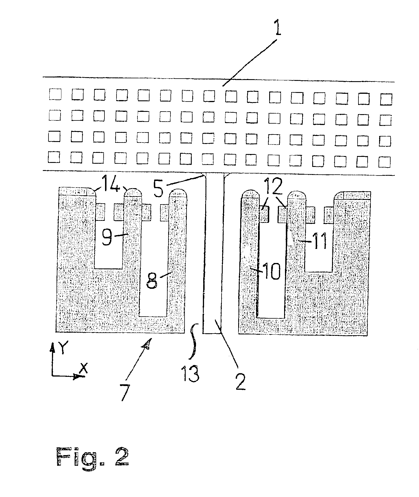
[0022]Each of the sensor structures depicted in FIGS. 1 through 5 is implemented in a micromechanical structural component, and includes parts that are movable in relation to the stationary substrate of the structural component, namely a seismic mass 1 and a spring system having at least one spring 2. In all drawings, the orientation of the X and Y axes is shown, while the Z axis is assumed to be oriented perpendicular to the page. Seismic mass 1 is connected to the substrate through a spring system, so that the distribution of mass of seismic mass 1 is asymmetrical in reference to the spring system. All of the sensor structures depicted in FIGS. 1 through 5 are designed for use in an acceleration sensor having horizontal and vertical sensitivity, in that the seismic mass 1 is designed in the form of a rocker and the spring system includes at least one torsion spring 2. Accelerations acting on the sensor structure are detected and determined in this case through the corresponding de...


PUM


Abstract

For a sensor whose sensor structure is implemented in a micromechanical structural component and which has parts which are movable in relation to the stationary substrate of the structural component, and which also includes an unsupported a seismic mass, a spring system having at least one spring, the seismic mass being connected to the substrate through the spring system, and an overload protection to limit the deflection of the spring system and the seismic mass in at least one direction, and an arrangement for detecting the deflections of the spring system and the seismic mass, whereby the impact forces may be reduced to prevent conchoidal breaks and resulting incipient damage to the sensor structure, as well as formation of particles. To that end, at least one two-dimensional stop for at least one moving part of the sensor structure is provided as overload protection. Alternatively or in addition thereto, at least one spring or resilient stop for at least one moving part of the sensor structure is provided as overload protection.

Description

FIELD OF THE INVENTION[0001]The present invention relates to a sensor whose sensor structure is implemented in a micromechanical structural component and has parts that are movable in relation to the stationary substrate of the structural component. The sensor structure includes at least one unsupported seismic mass and a spring system having at least one spring, the seismic mass being connected with the substrate through the spring system. The sensor structure also includes an overload protection device to limit the deflection of the spring system and the seismic mass in at least one direction. The sensor is also equipped with an arrangement means for detecting the deflections of the spring system and the seismic mass.BACKGROUND INFORMATION[0002]The seismic mass of that sensor is constructed in the form of a rocker which is both mechanically and electrically connected to the stationary substrate of the structural component. While the distribution of mass of the rocker is asymmetric...

Claims


Application Information

Patent Timeline
Patent Type & Authority Patents(United States)
IPC IPC(8): B81B3/00G01P15/08G01P15/125G01P15/02H01L29/84
CPCB81B3/0051G01P15/08G01P15/125B81B2201/0235B81B2203/051G01P2015/0817G01P2015/0831
Inventor FRANZ, JOCHENKOHN, OLIVERHENNING, FRANKMAUTE, MATTHIAS
Owner ROBERT BOSCH GMBH
Why Eureka
Try Eureka