Method for the decoupled control of the quadrature and the resonance frequency of a micro-mechanical gyroscope

a micro-mechanical gyroscope and quadrature technology, applied in the direction of speed/acceleration/shock measurement devices, instruments, surveying and navigation, etc., can solve the problems of undesired edge angles of the respective structures, measurement errors with respect, and reading-out direction deformations

Active Publication Date: 2013-08-08
CONTINENTAL TEVES AG & CO OHG
View PDF13 Cites 26 Cited by
  • Summary
  • Abstract
  • Description
  • Claims
  • Application Information

AI Technical Summary

Problems solved by technology

It is known that micro-mechanical springs for suspending seismic masses in rotation rate sensors to a certain extent already cause deflections in the reading-out direction in the drive mode or primary mode owing to relatively small fabrication inaccuracies which lead, in particular, to undesired edge angles of the respective structures without the presence of a rotation rate.
As a result, interference signals are generated which can be undesirably evaluated as rotation rate signal components and therefore falsify the rotation rate signal or cause a measuring error with respect to the rotation rate signal.
However, this quadrature suppression can undesirably influence the resonance frequency of the reading-out mode of the rotation rate sensor, as a result of which the differential frequency between the resonance frequencies is also changed with respect to the drive mode or primary mode and the reading-out mode or secondary mode of the rotation rate sensor.
This is all the more disadvantageous since the voltage which is applied to the trimming electrodes is included quadratically in the shifting of the resonance frequency of the reading-out mode.
However, this also usually influences the resonance frequency of the secondary oscillator, as well as influencing possible quadrature suppression.

Method used


Image

  • Method for the decoupled control of the quadrature and the resonance frequency of a micro-mechanical gyroscope
  • Method for the decoupled control of the quadrature and the resonance frequency of a micro-mechanical gyroscope
  • Method for the decoupled control of the quadrature and the resonance frequency of a micro-mechanical gyroscope

Examples


Embodiment Construction

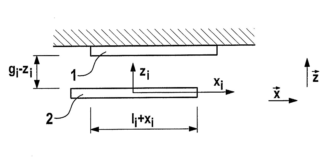
[0045]The exemplary capacitor illustrated in FIG. 1 and composed of a trimming electrode element 1 and mass electrode element 2 is as a parallel plate capacitor—wherein the distance or the distance across the gap gi is formed in the z direction between the two electrodes, and the deflection of the mass electrode element occurs in the x direction in the primary mode, wherein the change in the overlapping area occurs in the x direction, and the deflection of the mass electrode element occurs in the z direction in the secondary mode.

[0046]FIG. 3 illustrates, by way of example, the method and the rotation rate sensor according to concept A. The rotation rate sensor comprises a control arrangement 3 with which the electric trimming voltages u1, u2, u3, and u4 are adjusted, wherein the demodulated controlled variable Y is fed to a first controller unit 4, which controlled variable Y is acquired, in particular, from the original controlled variable y by means of demodulation 5 using two ha...


PUM


Abstract

A method for the precise measuring operation of a micro-mechanical rotation rate sensor, including at least one seismic mass, at least one drive device for driving the seismic mass in the primary mode (qi) and at least three trimming electrode elements which are jointly associated directly or indirectly with the seismic mass. An electric trimming voltage (u1, u2, u3, u4) is set respectively between said trimming electrode elements and the seismic mass. Each of the electric trimming voltages (u1, u2, u3, u4) are adjusted in accordance with a resonance frequency variable (ũT, ŨT,0), a quadrature variable (ũT, ŨT,0) and a restoring variable (ũS).

Description

CROSS REFERENCE TO RELATED APPLICATIONS[0001]This application is the U.S. National Phase Application of PCT International Application No. PCT / EP2011 / 054089, filed Mar. 17, 2011, which claims priority to German Patent Application No. 10 2010 002 973.4, filed Mar. 17, 2010, the contents of such applications being incorporated by reference herein.FIELD OF THE INVENTION[0002]The invention relates to a method according to precise measuring operation of a micro-mechanical rotation rate sensor, comprising at least one seismic mass, at least one drive device for driving the seismic mass in the primary mode (q1) and at least three trimming electrode elements which are jointly associated directly or indirectly with the seismic mass, wherein an electric trimming voltage (u1, u2, u3, u4) is applied between each of these individual trimming electrode elements and the seismic mass, and to a micro-mechanical rotation rate sensor having at least three trimming electrode elements which are jointly a...

Claims


Application Information

Patent Timeline
Patent Type & Authority Applications(United States)
IPC IPC(8): G01P15/125G01C19/56
CPCG01P15/125G01C19/56G01C19/5776G01C19/5726
Inventor EGRETZBERGER, MARKUSMAIR, FLORIANKUGI, ANDREAS
Owner CONTINENTAL TEVES AG & CO OHG
Why Eureka
Try Eureka