Vibrating micro-mechanical sensor of angular velocity

a micro-mechanical sensor and angular velocity technology, applied in the direction of acceleration measurement using interia force, turn-sensitive devices, instruments, etc., can solve the problems of disturbance of the motion of the detection resonator, angular vibration to be detected is susceptible to external mechanical interference, and the requirements are extremely tigh

Active Publication Date: 2010-09-02
MURATA MFG CO LTD
View PDF41 Cites 24 Cited by
  • Summary
  • Abstract
  • Description
  • Claims
  • Application Information

AI Technical Summary

Benefits of technology

[0018]The objective of the invention is to provide such an improved vibrating sensor of angular velocity, which enables measuring, reliably and with good performance, of angular velocity perpendicular to the surface plane, particularly in solutions of small vibrating sensors of angular velocity, and which, in comparison with prior art solutions with two masses, is remarkably much less sensitive to mechanical interference.

Problems solved by technology

Particularly in demanding applications, such as e.g. driving control systems in the car industry, these requirements are extremely tight.
The angular vibration to be detected is, however, susceptible to external mechanical interference.
Then the motion of the detection resonator is disturbed and deviations are caused to the output signal of the sensor of angular velocity, particularly when the frequency of the interference is close to the operating frequency of the sensor.
However, the greatest weakness of the reversed tuning fork principle is the primary motion's susceptibility to external disturbances.
Then, the linear acceleration along the primary axis can fairly easily disturb the operation of the sensor, since the masses are physically displaced, although the differential detection of them to a major extent mitigates the thereby caused signal.
Its greatest weakness is, however, an extremely complicated and bulky spring structure.
The excitation structures are also difficult to design and they also take a lot of space.
Another significant challenge in designing a good sensor of angular velocity is the capacitive crosstalk of electrostatic drive, particularly into Coriolis detection.
This causes a disturbance in the value of the zero point of the sensor dependent on the amplitude of the drive signal, which causes an error dependent on i.a. the temperature.
However, carrier detection complicates the already quite complicated electronics of the sensor of angular velocity, which then contributes to increasing cost and size of the electronics and impairs its reliability.

Method used


Image

  • Vibrating micro-mechanical sensor of angular velocity
  • Vibrating micro-mechanical sensor of angular velocity
  • Vibrating micro-mechanical sensor of angular velocity

Examples


Embodiment Construction

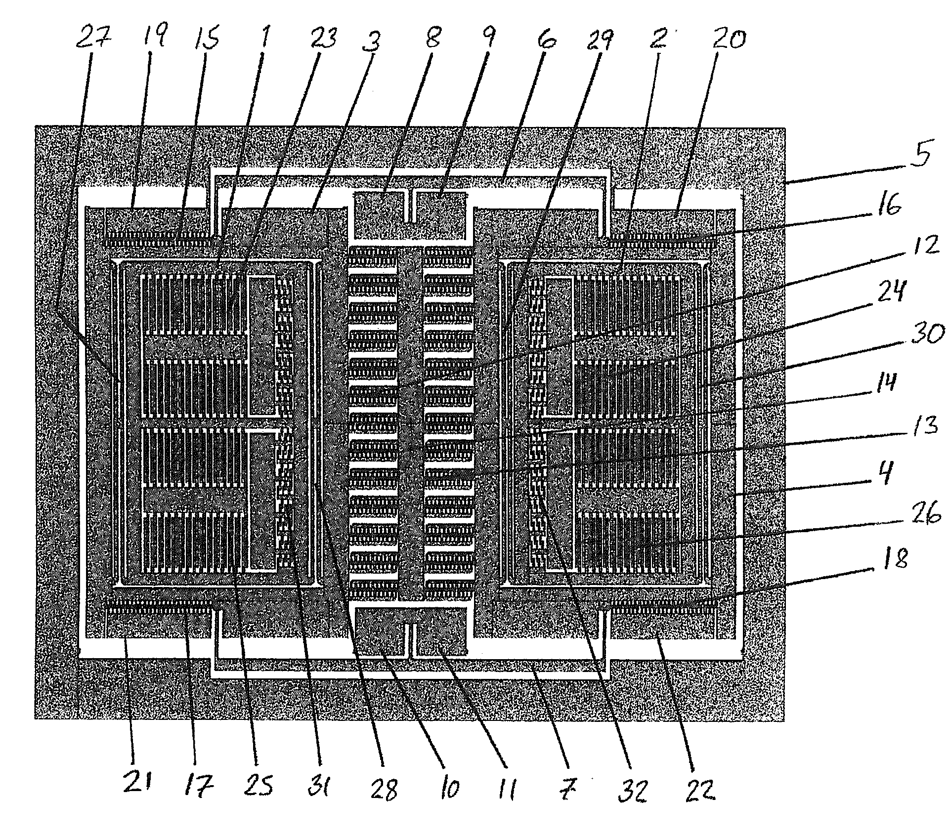
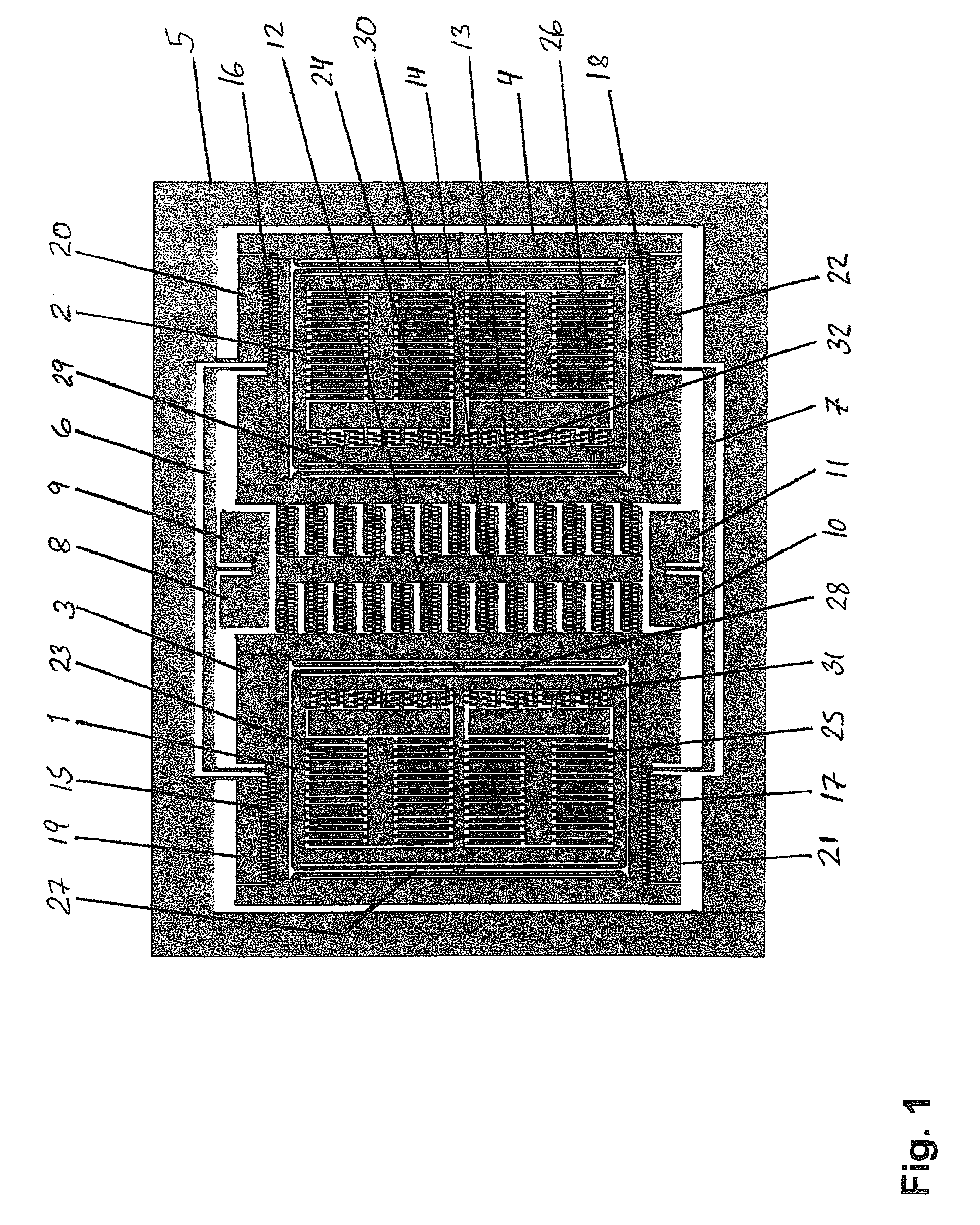
[0029]FIG. 1 shows a diagram of the functional structure of a vibrating micro-mechanical sensor of angular velocity according to the invention. The depicted vibrating micro-mechanical sensor of angular velocity according to the invention comprises two mass structures 1, 2 positioned apart, which mass structures 1, 2 are supported to excitation structures 3, 4 by means of springs 27-30. Said excitation structures 3, 4 are supported by means of coupling seesaw type springs 6, 7 to anchoring points 8-11 of a frame 5 bordering the sensor.

[0030]The vibrating micro-mechanical sensor of angular velocity according to the invention further comprises capacitive comb structures 23-26 supported to the seismic masses 1, 2, and excitation comb structures 12, 13 connected to the excitation structures 3, 4. Said excitation comb structures 12, 13 are positioned between the excitation structures 3, 4 comprising the mass structures 1, 2, and said excitation comb structures 12, 13 are supported to a ce...


PUM


Abstract

The invention relates to measuring devices used for measuring angular velocity, and more precisely, to vibrating micro-mechanical sensors of angular velocity. The sensor of angular velocity according to the invention comprises at least two seismic mass structures (1), (2), excitation structures (3), (4) and coupling seesaw type springs (6), (7). The objective of the invention is to provide an improved sensor structure, which enables reliable measuring with good efficiency particularly in small vibrating micro-mechanical angular velocity sensor solutions.

Description

FIELD OF THE INVENTION[0001]The invention relates to measuring devices used for the measuring of angular velocity, and, more precisely, to vibrating micro-mechanical sensors of angular velocity. The object of the invention is to provide an improved sensor structure enabling reliable measuring with good efficiency particularly in small vibrating micro-mechanical angular velocity sensor solutions.BACKGROUND OF THE INVENTION[0002]Measuring based on a vibrating sensor of angular velocity has proved to be a method of measuring angular velocity having a simple concept and being reliable. In a vibrating sensor of angular velocity, a certain known primary motion is produced and it is maintained in the sensor. The motion desired to be measured with the sensor is then detected as a deviation of the primary motion.[0003]Central features required of sensors of angular velocity are resistance to shaking and impact. Particularly in demanding applications, such as e.g. driving control systems in t...

Claims


Application Information

Patent Timeline
Patent Type & Authority Applications(United States)
IPC IPC(8): G01C19/56
CPCG01C19/5747B81B3/00G01C21/10G01P3/14B81B3/0018G01C19/56G01C19/5607
Inventor BLOMQVIST, ANSSIRUOHIO, JAAKKO
Owner MURATA MFG CO LTD
Why Eureka
Try Eureka