Gyroscope structure and gyroscope

a gyroscope and structure technology, applied in the field of microelectromechanical devices, can solve the problems of many mems gyro designs, low signal generation, and complex gyroscopes, and achieve the effects of less sensitive to deformation, easy system implementation, and higher signal level

Active Publication Date: 2015-03-12
MURATA MFG CO LTD
View PDF30 Cites 25 Cited by
  • Summary
  • Abstract
  • Description
  • Claims
  • Application Information

AI Technical Summary

Benefits of technology

[0016]The present invention is based on applying a new combination of primary motion and secondary motion modes of two planar seismic masses. In the primary motion, the seismic masses are excited to an opposite phase rotary oscillation about a common primary axis. A secondary motion of each of the seismic masses includes in-plane rotary oscillation about a detection axis that is perpendicular to the plane formed by the seismic masses. The detection a...

Problems solved by technology

In MEMS gyros the primary motion is typically not continuous rotation as in conventional ones due to lack of adequate bearings.
Gyroscopes are very complex inertial MEMS sensors.
The basic challenge in gyroscope designs is that the Coriolis force is very small and therefore the generated signals tend to be minuscule compared to other electrical signals present in the gyroscope.
Spurious response...

Method used


Image

  • Gyroscope structure and gyroscope
  • Gyroscope structure and gyroscope
  • Gyroscope structure and gyroscope

Examples


Embodiment Construction

[0021]The following embodiments are exemplary. Although the specification may refer to “an”, “one”, or “some” embodiment(s), this does not necessarily mean that each such reference is to the same embodiment(s), or that the feature only applies to a single embodiment. Single features of different embodiments may be combined to provide further embodiments.

[0022]In the following, features of the invention will be described with a simple example of a device architecture in which various embodiments of the invention may be implemented. Only elements relevant for illustrating the embodiments are described in detail. Various implementations of gyroscope structures that are generally known to a person skilled in the art may not be specifically described herein.

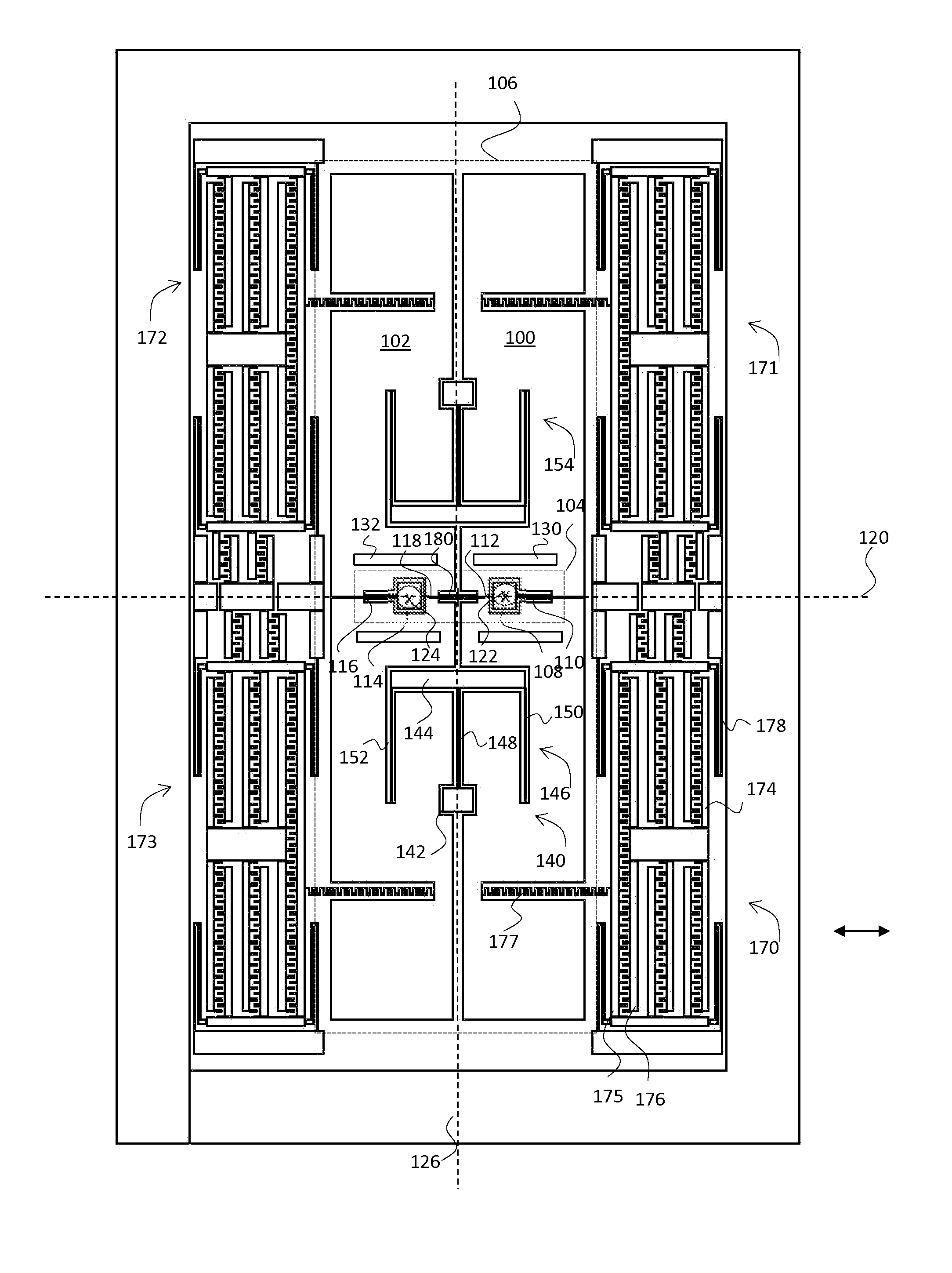
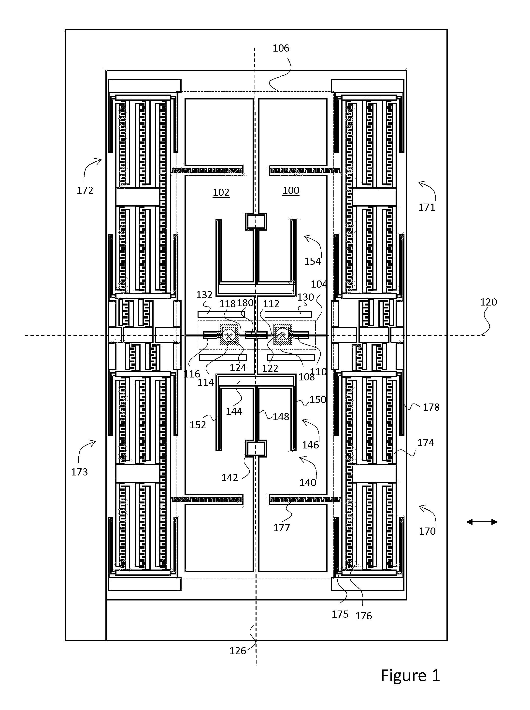
[0023]FIG. 1 illustrates an embodiment of a gyroscope structure according to the present invention with elements of a structure wafer of a MEMS gyroscope. The gyroscope structure includes a first seismic mass 100 and a second seismic ...


PUM


Abstract

A microelectromechanical gyroscope that comprises two seismic masses suspended to form a plane of masses. The seismic masses are excited into rotary oscillation about a common primary axis that is in the plane of masses. Detected angular motion causes a rotary oscillation of the first seismic mass about a first detection axis, and of the second seismic mass about a second detection axis. The detection axes are perpendicular to the plane of masses and separated by a non-zero distance.

Description

BACKGROUND[0001]1. Field[0002]The present invention relates to microelectromechanical devices and especially to a gyroscope structure and a gyroscope, as defined in the preambles of the independent claims.[0003]2. Description of the Related Art[0004]Micro-Electro-Mechanical Systems, or MEMS can be defined as miniaturized mechanical and electro-mechanical systems where at least some elements have a mechanical functionality. Since MEMS devices are created with the same tools used to create integrated circuits, micromachines and microelectronics can be fabricated on the same piece of silicon to enable advanced devices.[0005]MEMS structures can be applied to quickly and accurately detect very small changes in physical properties. For example, a microelectromechanical gyroscope can be applied to quickly and accurately detect very small angular displacements. Motion has six degrees of freedom: translations in three orthogonal directions and rotations around three orthogonal axes. The latt...

Claims


Application Information

Patent Timeline
IPC IPC(8): B81B7/00G01C19/5712
CPCB81B7/0058B81B2201/0242G01C19/5712G01C19/5621G01C19/5656G01C19/574G01P15/125
Inventor BLOMQVIST, ANSSIRUOHIO, JAAKKO
Owner MURATA MFG CO LTD
Why Eureka
Try Eureka